semi合集-English.pdf - 第1468页
SEMI 30.1-0200 © SEMI 1998, 2000 43 • “M21” layouts are establis hed within the M20P coo rdinate system and need not require any additional alignment site data than is needed to establish the M20P coordinate system. Howe…

SEMI 30.1-0200 © SEMI 1998, 2000 42
than relative to the substrate shape and dimensions.
ISEM also defines the M20P coordinate system to be
one which is designed to be “parallel” to the SEMI M20
coordinate system. In practice, because of experimental
errors, both the origins and the axes may differ slightly
from their intended values of a simple translation and
no rotation. Equipment should be designed to be able to
locate the alignment sites, given the various possible
experimental errors.
R1-3.3 Establishing an M20P Coordinate System — A
minimum of two alignment sites is necessary to
establish an M20P coordinate system on a substrate.
Additional sites are often used to determine a scaling
ratio of the dimensions of the actual coordinate system
relative to the dimensions of the expected coordinate
system and are reported using the ISEM data item of
ScaleFactor.
XlateData is used to report actual coordinate system
location. Most equipment cannot distinguish whether
patterned substrate site location errors are due to the
substrate, the layout on the substrate, or the
equipment’s ability to locate the sites. However,
information that is available through the use of
patterned-substrate alignment sites can provide a means
for identifying potential equipment problems. For
instance, assume that the only pattern-layout location
error on a substrate is that due to the establishment of
the location of the substrate center and fiducial. For
many users and equipment systems, this is a good
assumption. If this is the case, then the ISEM data item
named XlateData can be used to track this error.
Although the error may result from multiple sources,
being able to track it on various equipment will enable
users to apply statistical process control techniques to
identify the specific sources.
Offset sites may be found by equipment at actual
locations which deviate from their expected locations
through either pattern layout errors or equipment
“stage” or imaging errors. Again, in a controlled
manufacturing process, these combined errors should
be normally distributed, and non-normal deviations
may indicate possible equipment problems. The actual
position of a site relative to its expected position shall
be reported through the use of the ISEM data item
named Offset.
R1-4 Layout of Rectangular Pattern Elements
on a Substrate Using SEMI M20 Coordinate
System
Equipment shall be capable of routine, automated
operation without needing substrate layout information
(e.g., field or die maps). However, having the capability
to provide substrate layout information to equipment
from the host can be desirable. ISEM defines a means
to do this in this section for substrates, based on SEMI
M21 (Specification for Assigning Addresses to
Rectangular Elements in a Cartesian Array.) The SEMI
M21 standard is limited to defining how to assign
“addresses” to elements and how to find the “array
center” element. It does not specify how the rectangular
pattern-elements are located on the substrate. In this
section, ISEM defines how these pattern-elements are
located on a substrate, using the data item named
M21Data, and how to establish within-element
coordinate systems. Any additional layout information,
such as within-element structure details or element
attribute information, is beyond the scope of ISEM.
R1-4.1 ISEM “M21” Layouts
• An “M21” layout consists of an array of equal-
sized rectangular pattern-elements with no space
between the pattern elements.
• ISEM defines the “M21” layout on a substrate to
include all pattern-elements which are either
wholly or partially within the circumference of the
substrate.
• The ISEM approach is to define the pattern map by
specifying the M20P coordinate for the lower left
corner of the minimum number of pattern-elements
needed to define the layout, along with the pattern-
element addresses (names). For a non-tiled layout,
the location and name of a single pattern-element is
sufficient to establish the “M21” layout. For tiled
layouts, the location and name of one pattern-
element in each row or column are required. Note
that the location of the lower left corner of some
pattern-elements may be outside the circumference
of the substrate.
• The “M21” pattern-element coordinate system
shall have its x and y axes parallel to the respective
M20P coordinate system axes and shall have their
origins at the lower left corner of each element.
The pattern-element coordinate system shall have a
name and a specific pattern-element address
identifier per SEMI M21.
• Layout definition is supported only for host-to-
equipment communications. The user is
responsible for ensuring that the pattern-element
addresses provided to the equipment agree with the
SEMI M21 specification. The equipment need not
check this, other than to ensure that there are not
conflicts within the provided layout, and shall
report results with pattern-element addresses as
provided by the user.
SEMI 30.1-0200 © SEMI 1998, 200043
• “M21” layouts are established within the M20P coordinate system and need not require any additional
alignment site data than is needed to establish the M20P coordinate system. However, as with M20P, additional
alignment may be necessary because of errors in either the pattern layout or the equipment’s ability to locate
features. Offset shall be used to report the location corrections that result from any within-element alignments.
R1-5 How an M20P Coordinate System Is Established on a Substrate
The following example is fairly basic. For this example, the M20P coordinate system has a zero translation from the
SEMI M20 coordinate system. Also, the equipment documentation states that 4 alignment sites are required. The
equipment does M20P alignment on two alignment sites and does a low resolution and then a high resolution
alignment at each site. Note that the specific alignment point is different at the two resolutions, so the coordinates
are slightly different. The alignment sites are defined to the equipment via the process program class named
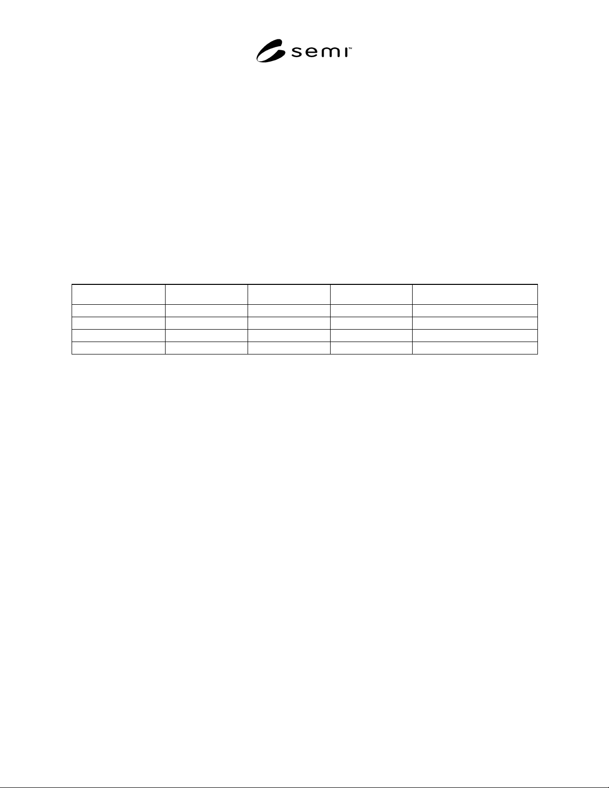
“TABLE-ALIGN-DEF”, as detailed below. The order of the sites in “TABLE-ALIGN-DEF” is not important. The
sites are then selected via the CPNAME named “ALIGNLIST”, which is included in the PP-SELECT command.
The order of the sites listed in “ALIGNLIST” is important and is as-specified in the equipment’s documentation.
The first item is the alignment site for the first low resolution site, the second item is for the first high resolution site,
the third item is the second low resolution site, and the fourth is the second high resolution site.
“TABLE-ALIGN-DEF”
AlignName Coordx Coordy Coordsys Attribute (1)
Coarse1 -60000 -200 “M20P”
Fine1 -60020 -205 “M20P”
Coarse2 +60000 +200 “M20P”
Fine2 +59980 +195 “M20P”
“ALIGNNAME”
L,4
1. <Coarse1>
2. <Fine1>
3. <Coarse2>
4. <Fine2>
Using this information, the equipment will go to the nominal “M20” location for Coarse1, then “find” where it
actually is. The offset between the nominal “M20” location and the actual “M20” location is then used to “find”
Fine1. The actual M20 location of Fine1 is saved. The process is then repeated for Coarse2 and Fine2. The
equipment can now determine the “M20” to M20P offset from the nominal and actual coordinates. First, a summary
of the data:
xN1 = -60020 yN1 = -205 Nominal x and y data for the first fine site
xA1 = -59800 yA1 = -150 Actual x and y data for the first fine site
xN2 = +59980 yN2 = +195 Nominal x and y data for the second fine site
xA2 = +60060 yA2 = +175 Actual x and y data for the second fine site
SEMI 30.1-0200 © SEMI 1998, 2000 44
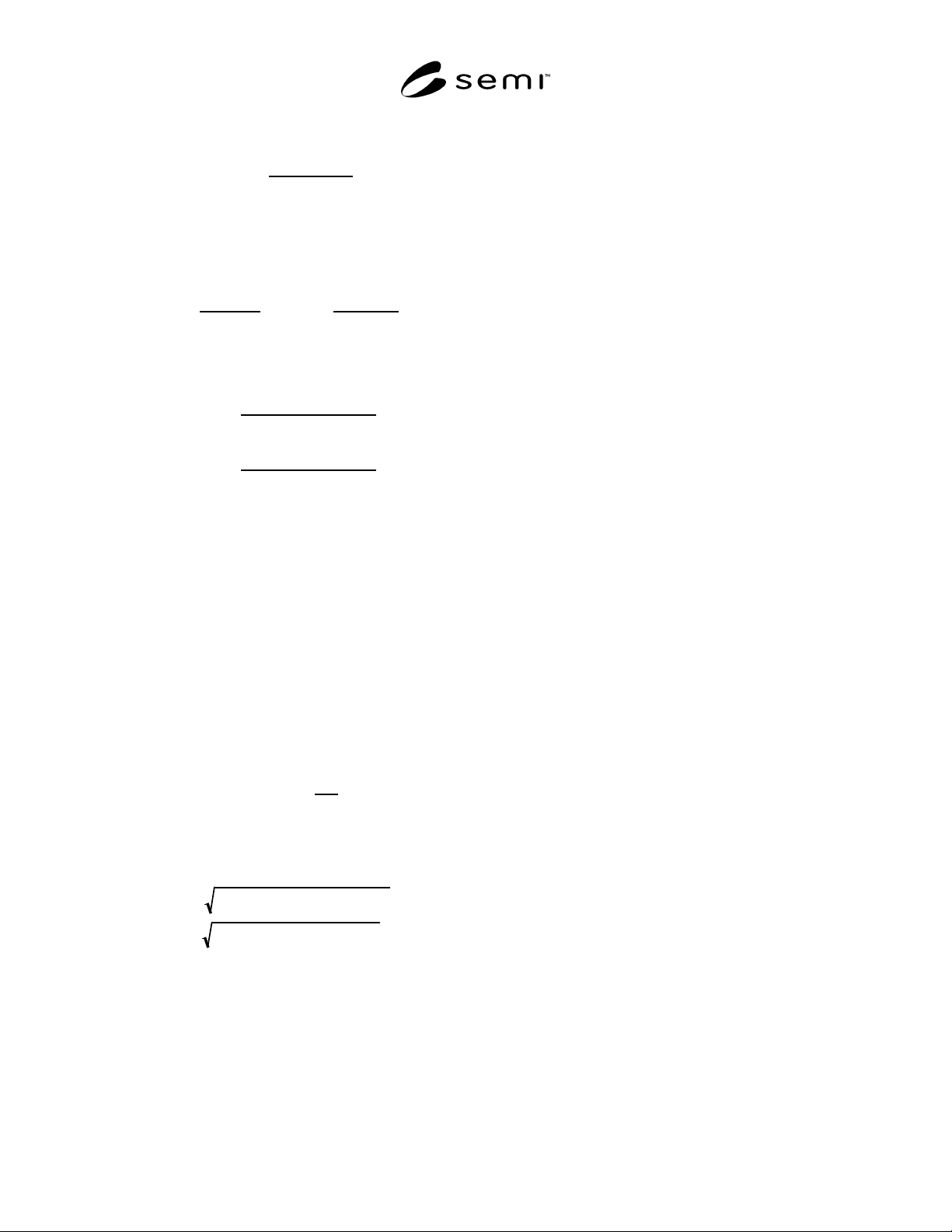
The equipment first calculates Theta, using, for
example, the formula:
Θ=tan
−1
M
A −
M
N
1+ MA MN
where MA and MN are, respectively, the slopes of the
lines connecting the two actual fine sites and the line
connecting the two nominal sites, in “M20”
coordinates, calculated as follows:
MA =
yA
2
− yA
1
xA
2
− xA
1
MN =
yN
2
− yN
1
xN
2
− xN
1
The equipment then calculates DeltaX and DeltaY,
using, for example, the formulas:
DeltaX =
Csin Θ()+ Dcos Θ()
sin Θ()
()
2
+ cos Θ()
()
2
DeltaY =
Csin Θ
()− Dcos Θ()
sin Θ()()
2
+ cos Θ()()
2
where C and D, the adjusted site 1 coordinates in a
rotation-adjusted coordinate system, are calculated,
for example, using the formulas:
C
= yA1 − ((
xN
1 sinΘ ) + ((y
N
1 cosΘ)
D = xA1 − ((xN1 cosΘ) − ((yN1 sinΘ)
The equipment can also calculate a ScaleFactor term
to indicate the relative ratio between the length of the
vector connecting the nominal alignment sites and the
length of the vector connecting the actual alignment
sites. This can be used, for example, to judge whether
there is a problem with the alignment process, since
the difference between these two vectors should be
small.
ScaleFactor =
VA
V
N
where VA and VN are the length of the vectors
connecting the actual and nominal alignment sites,
calculated using the formulas:
VN = yN
2
− yN
1
()
2
+ xN
2
− xN
1
()
2
VA = yA
2
− yA
1
()
2
+ xA
2
− xA
1
()
2