semi合集-English.pdf - 第1586页
SEMI E37-0303 © SEMI 1995, 2003 8 7.5 Linktest Procedure — The Linktest is used to determine the operatio nal integrity of TCP/IP and HSMS communications. Its use is valid an ytime in the CONNECTED state. 7.5.1 Initiator…
SEMI E37-0303 © SEM 1995, 2003 7
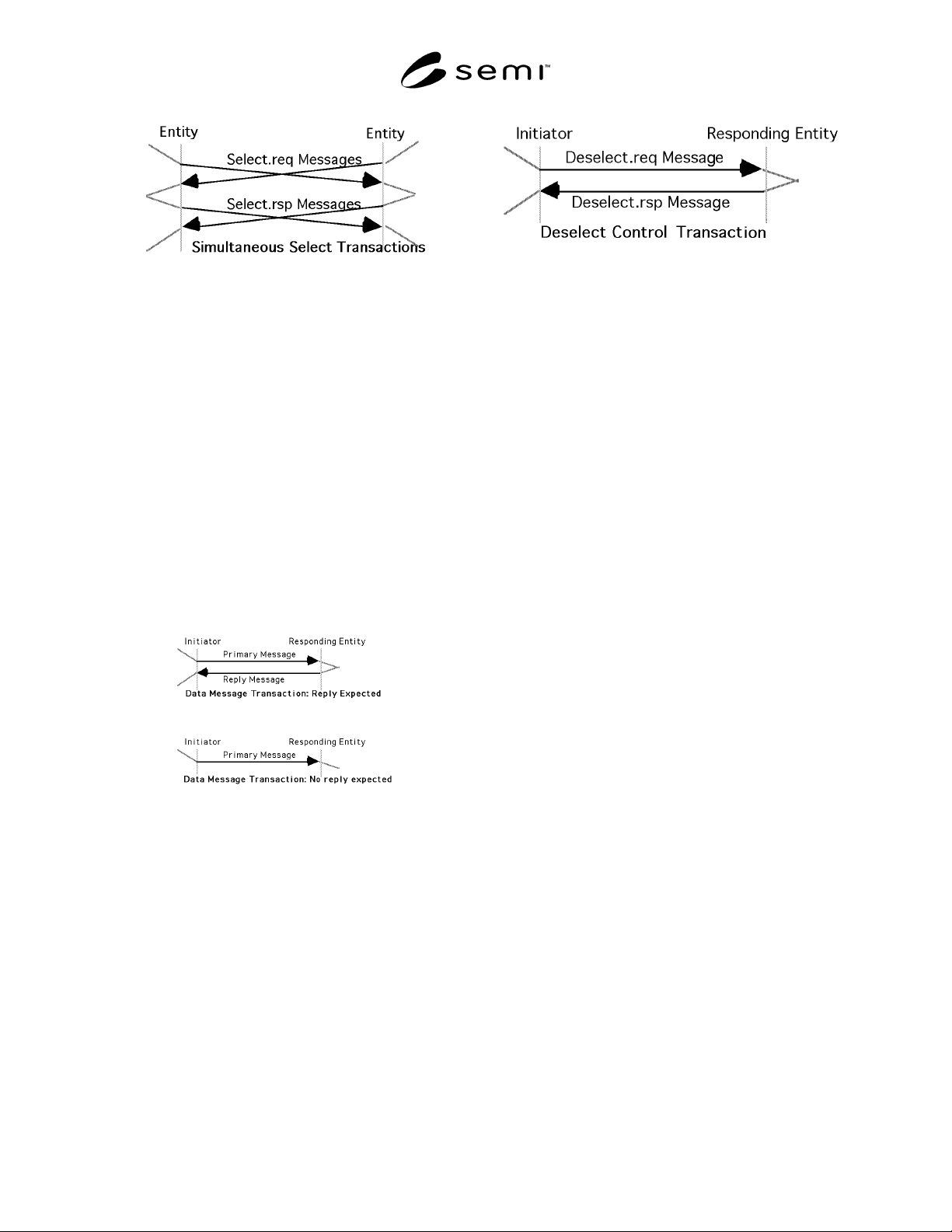
7.3 Data Procedure — HSMS data messages may be
initiated by either entity as long as the connection is in
the SELECTED state. Receipt of a data message when
not in the SELECTED state will result in a reject
procedure (see Section 7.7).
Data messages may be further defined as part of a data
transaction as either a “Primary” or “Reply” data
message. In a data transaction, the initiator of the
transaction sends a primary message to the responding
entity. If the Primary message indicates that a reply is
expected, a Reply message is sent by the responding
entity in response to the Primary.
The following types of Data Transactions are
supported:
1. Primary Message with reply expected and the
associated Reply Message.
2. Primary Message with no reply expected.
The specific procedures for these transactions are
determined by the application layer and are subject to
other standards (for example, E5 and E30 for GEM
equipment using SECS-II encoded messages).
The applicable upper layer standard is identified by the
message type. The type is determined from the specific
format defined in Section 8. The normal type for HSMS
messages is SECS-II text. Also refer to “Special
Considerations” concerning the T3 Reply Timeout.
7.4 Deselect Procedure — The Deselect procedure is
used to provide a graceful end to HSMS
communication for an entity prior to breaking the
TCP/IP connection. HSMS requires that the connection
be in the SELECTED state. The procedure is as
follows.
7.4.1 Initiator Procedure
1. The initiator of the Deselect procedure sends the
Deselect.req message to the responding entity.
2. If the initiator receives a Deselect.rsp with a
Deselect Status of 0, its Deselect procedure
terminates successfully. The NOT SELECTED
state is entered (see Section 5).
3. If the initiator receives a Deselect.rsp with a non-
zero Deselect Status, its Deselect procedure
terminates unsuccessfully. No state change occurs.
4. If the T6 timeout expires in the initiator before
receipt of a Deselect.rsp, it is considered a
communications failure (see “Special
Considerations”).
7.4.2 Responding Entity Procedure
1. The responding entity receives the Deselect.req
message.
2. If the responding entity is in the SELECTED state,
and if it is able to permit the Deselect, it responds
using the Deselect.rsp with a zero response code.
The responding entity' s Deselect procedure
completes successfully. The NOT SELECTED
state is entered (see Section 5).
3. If the responding entity is unable to permit the
Deselect, either because it is not in the SELECTED
state or because local conditions do not permit the
Deselect, it responds using the Deselect.rsp with a
non-zero response code. The responding entity' s
Deselect procedure terminates unsuccessfully. No
state change occurs.
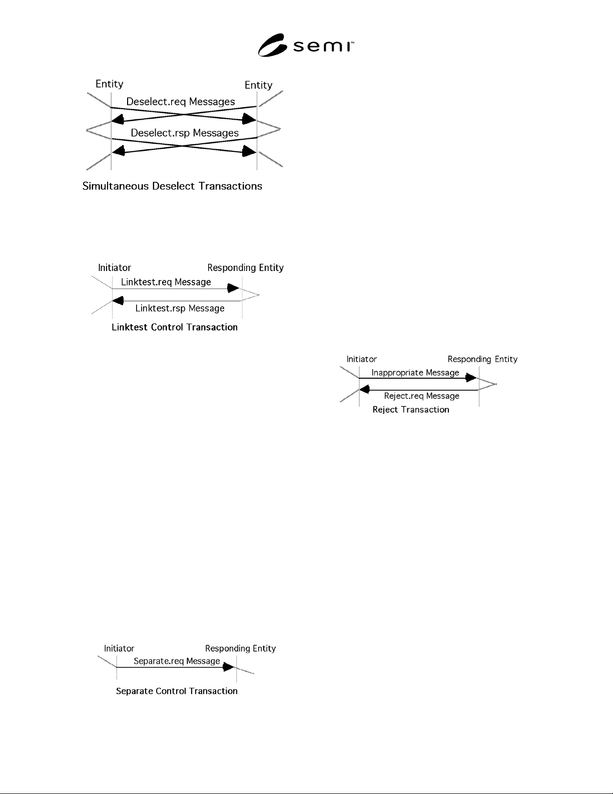
7.4.3 Simultaneous Deselect Procedures — If the
subsidiary standards do not restrict the use of the
Deselect, it is possible that both entities simultaneously
initiate Deselect Procedures with identical SessionID’s.
In such a case, each entity will accept the other entity' s
Deselect request by responding with the deselect.rsp.
SEMI E37-0303 © SEMI 1995, 2003 8
7.5 Linktest Procedure — The Linktest is used to
determine the operational integrity of TCP/IP and
HSMS communications. Its use is valid anytime in the
CONNECTED state.
7.5.1 Initiator Procedure
1. The initiator of the Linktest procedure sends the
Linktest.req message to the responding entity.
2. If the initiator receives a Linktest.rsp within the T6
timeout, the Linktest is successfully completed.
3. If the T6 timeout expires in the initiator before
receipt of a Linktest.rsp, it is considered a
communications failure (see “Special
Considerations”).
7.5.2 Responding Entity Procedure
1. The responding entity receives the Linktest.req
from the initiator.
2. The responding entity sends a Linktest.rsp.
7.6 Separate Procedure — The Separate procedure is
used to abruptly terminate HSMS communication for
an entity prior to breaking the TCP/IP Connection.
HSMS requires that the connection be in the
SELECTED state when using Separate. The responding
entity does not send a response and is required to
terminate communications regardless of its local state.
The procedure is as follows.
7.6.1 Initiator Procedure
1. The initiator of the select procedure sends the
Separate.req message to the responding entity. The
initiator' s Separate procedure completes
successfully. The NOT SELECTED state is entered
(see Section 5).
7.6.2 Responding Entity Procedure
1. The responding entity receives the Separate.req
from the initiator.
2. If the responding entity is in the SELECTED state,
its Separate procedure completes successfully.
3. If the responding entity is not in the SELECTED
state, the Separate.req is ignored.
7.7 Reject Procedure — The Reject procedure is used
in response to an otherwise valid HSMS message
received in an inappropriate context. Supporting the
reject procedure can provide useful diagnostic
information during the development of a distributed
application using HSMS. The procedure is as follows:
7.7.1 Initiator (Sender of Inappropriate Message)
Procedure
1. The initiator of the inappropriate message, upon
receiving the Reject.req, takes appropriate action
(local entity-specific).
7.7.2 Responding Entity Procedure
1. The entity receiving the inappropriate message
responds with a Reject.req message.
HSMS requires the reject procedure for the receipt of a
data message in the NOT SELECTED state, or the
receipt of a message whose SType or PType (see next
section: Message Format) is not defined for the entity
receiving the message. Subsidiary standards may define
other conditions which require the Reject Procedure. In
general, receipt of a reject message is an indication of
an improperly configured system or a software
programming error.
8 HSMS Message Format
This section defines the detailed format of the messages
used by the procedures in the previous section.
SEMI E37-0303 © SEM 1995, 2003 9
8.1 General Message Format
8.1.1 Byte Structure — Within HSMS, a byte contains
eight (8) bits. The bits in a byte are numbered from Bit
7 (most significant) to Bit 0 (least significant).
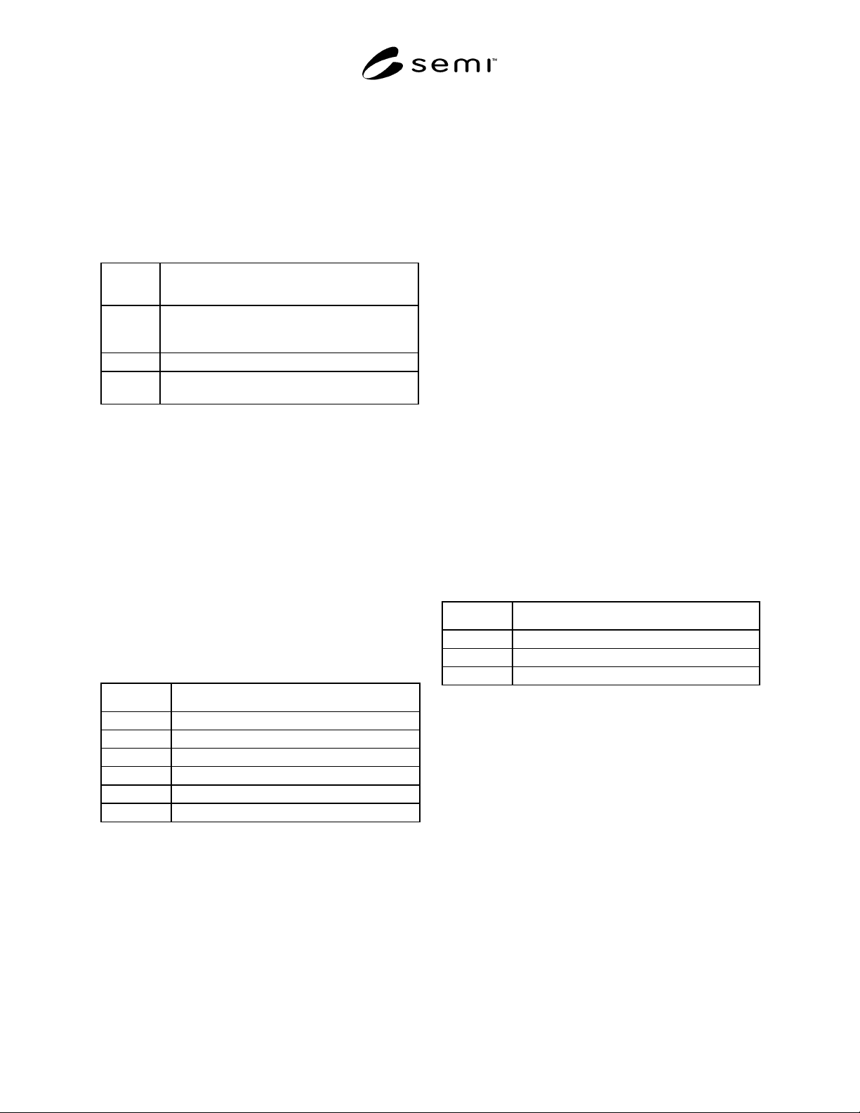
8.1.2 Message Format — An HSMS Message is
transmitted as a single contiguous stream of bytes in the
following order:
Table 2 HSMS Message Format
Number
of Bytes
Description
4 Bytes Message Length. MSB First. Specifies the
number of bytes in the Message Header plus the
Message Text.
10 Bytes Message Header.
0–n Bytes Message Text. Format is further specified by
PType field of message header.
8.1.3 Message Length — Message Length is a four-
byte unsigned integer value which specifies the length
in bytes of the Message Header plus the Message Text.
Message Length is transmitted most significant byte
(MSB) first and least significant byte (LSB) last.
The minimum possible Message Length is 10 (Header
only). The maximum possible Message Length is
implementation-specific.
8.1.4 Message Header — The Message Header is a ten-
byte field. The bytes in the header are numbered from
byte 0 (first byte transmitted) to byte 9 (last byte
transmitted). The format of the Message Header is as
follows:
Table 3 HSMS Message Header
Bytes Description
0–1 Session ID (Device ID)
2 Header Byte 2
3 Header Byte 3
4 PType
5 SType
6–9 System Bytes
The physical byte order is designed to correspond as
closely as possible to the SECS-I header.
8.1.4.1 Session ID — Session ID is a 16-bit unsigned
integer value, which occupies bytes 0 and 1 of the
header (byte 0 is MSB, 1 is LSB). Its purpose is to
provide an association by reference between control
messages (particularly Select and Deselect) and
subsequent data messages. It is the role of HSMS
subsidiary standards to specify this association further.
8.1.4.2 Header Byte 2 — This header byte is used in
different ways for different HSMS messages. For
Control Messages (see SType, below) it contains zero
or a status code. For a Data Message whose PType (see
below) = 0, it contains the W-Bit and SECS Stream.
For a Data Message with PType not equal to 0, see
“Special Considerations.”
8.1.4.3 Header Byte 3 — This header byte is used in
different ways for different HSMS messages. For
Control Messages, it contains zero or a status code. For
a Data Message whose PType (see below) = 0, it
contains the SECS Function. For a Data Message with
PType not equal to 0, see “Special Considerations.”
8.1.4.4 PType — PType (Presentation Type) is an 8-bit
unsigned integer value which occupies byte 4 of the
header. PType is intended as an enumerated type
defining the presentation layer message type: how the
Message Header and Message Text are encoded. Only
PType = 0 is defined by HSMS to mean SECS-II
message encoding. For non-zero PType values, see
“Special Considerations.”
Table 4 PType
Value Description
0 SECS-II Encoding
1–127 Reserved for subsidiary standards
128–255 Reserved, not used
8.1.4.5 SType — SType (Session Type) is a one-byte
unsigned integer value which occupies header byte 5.
SType is an enumerated type identifying whether this
message is an HSMS Data Message (value = 0) or one
of the HSMS Control Messages (other). Those values
not explicitly defined in the table are addressed in
“Special Considerations.”