semi合集-English.pdf - 第164页
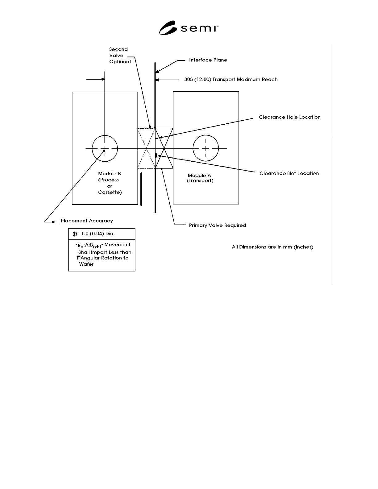
SEMI E21-94 © SEMI 1991, 2002 4 Figure 1 Module Interface with Wafer Trans p ort and Placement Detail (Plan View)

SEMI E21-94 © SEMI 1991, 2002 3
provided in the O-ring flange face as shown in Figure 1
and specified in Figure 3. Alignment pin height above
the flange face is 6 mm (0.24 in.) minimum to 8 mm
(0.31 in.) maximum (see Section R1-6).
6.2.4 Isolation Valves — The transport module is
always equipped with a valve for environmental
isolation at each module interface plane. The intratool
transport port on a process or cassette module may be
equipped with an environmental isolation valve (see
Section R1-7).
6.3 Flange — A flange is specified as 162 mm (6.378
in.) by 340 mm (13.386 in.). One horizontal edge is
specified to be 50 mm (1.969 in.) from the alignment
pins’ centerline (see Figure 4).
6.3.1 Clamping — Clamping grooves as specified in
the International Standards Organization document,
Vacuum Technology, Flange Dimensions (ISO 1609-
1986), Table 2, nominal bores 40 mm-250 mm (1.575
in.Ð9.843 in.) are located at the flange perimeter (see
groove detail in Figure 4). Clamps for ISO flanges can
be used to generate the force necessary to produce an
environmental seal (see Section R1-8).
6.3.2 Non-Flanged Surfaces — A non-flanged surface
may be used to join with a flanged surface. An
attachment means to engage the flange must be
provided. If a flanged adaptor piece is necessary to join
two non-flanged surfaces, then the adaptor piece shall
be located on the process or cassette side of the
interface plane.
LIST OF FIGURES
Figure 1 — Module Interface with Wafer Transport and
Placement Detail (Plan View)
Figure 2 — Wafer Transport Plane Elevation
Figure 3 — Interface Plane
Figure 4 — Flange Specification
SEMI E21-94 © SEMI 1991, 2002 4
Figure 1
Module Interface with Wafer Transport and Placement Detail (Plan View)
SEMI E21-94 © SEMI 1991, 2002 5
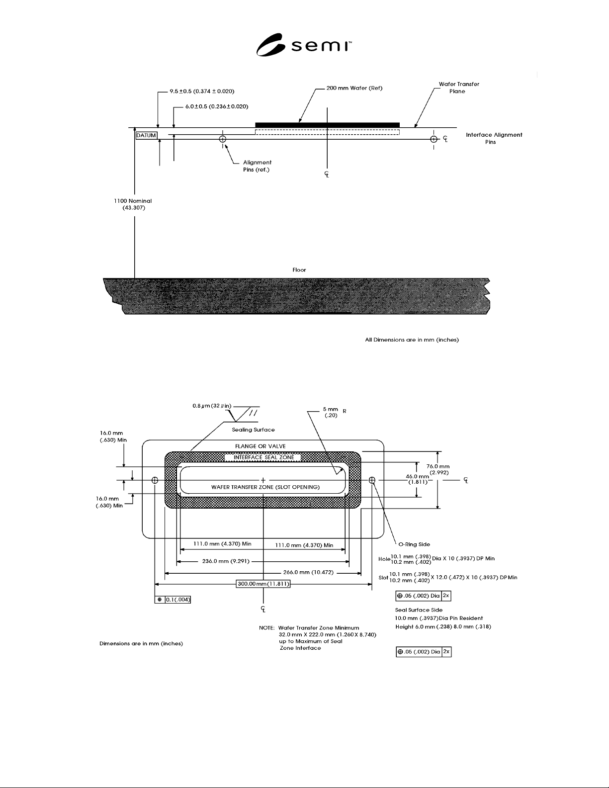
Figure 2
Wafer Transport Plane Elevation
Figure 3
Interface Plane