semi合集-English.pdf - 第1897页
SEMI E54.1-1000 © SEMI 1996, 2000 3 Figure 2 Examples of Devices 5.2.5 dat a type — An un signed shor t integer formatted as an enumerated by te to specify attribute data format. The intended us e o f this attribute type…
SEMI E54.1-1000 © SEMI 1996, 2000 2
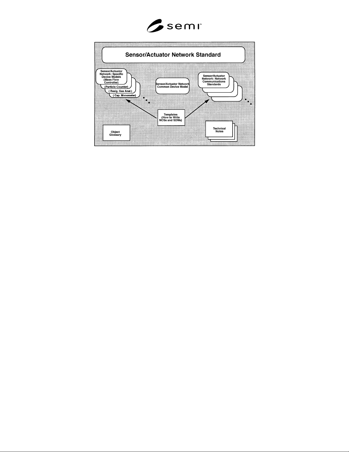
Figure 1
Sensor/Actuator Network-Related Documents
5 Terminology
Terminology may be reproduced here which is defined
in other SEMI documents.
5.1 Device Component Terminology
5.1.1 attribute — Externally visible information
concerning an object.
5.1.2 behavior — A specification of how an object
acts. Actions result from different events the object
detects, such as receiving service request, detecting
internal faults, or elapsing timers.
5.1.3 class — A specific type or classification of
objects.
5.1.4 device — A tangible thing consisting of: (1) at
least one sensor and/or actuator and/or controller, (2) a
communications controller which supports a single
point of access to a network as specified in this docu-
ment, and (3) interconnection and management hard-
ware and software that provides for the consolidation of
(1) and (2) into a system that has the capability to
comply with the specification detailed in this document.
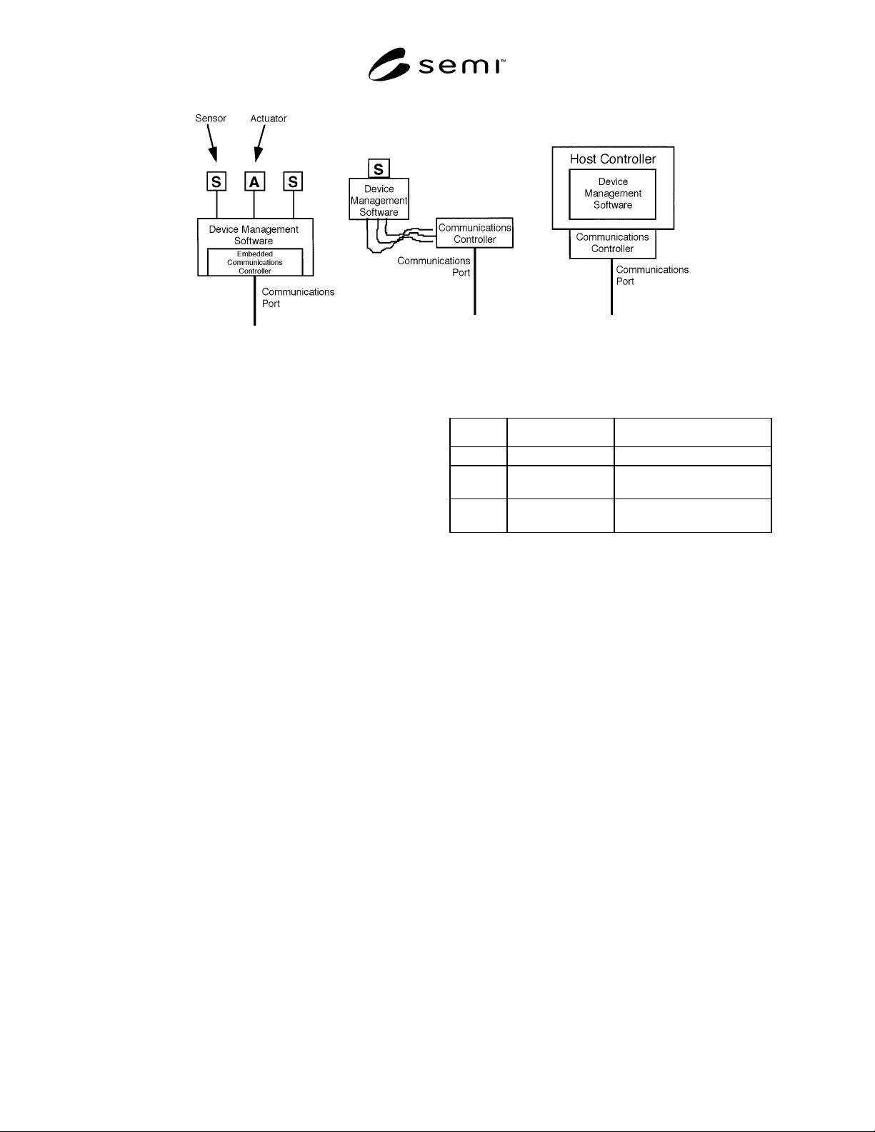
Examples of devices are given in Figure 2.
5.1.5 device model — An abstractio n of a device for
the purpose of understanding it before building it or
using it.
5.1.6 embedded object — An embedded object is sim-
ilar in functionality or purpose to the object in which it
is embedded, or supports the functionality of the object
in which it is embedded. The embedding construct is
utilized solely for purposes of documentation structure
and understanding. As such, it does not imply any
direct relationship, inheritance, similarity in structure,
or connectivity in addressing scheme between the em-
bedded object and the object in which it is embedded.
5.1.7 instance — A specific and real occurrence of an
object.
5.1.8 manufacturer — In the context of this document,
this refers to the manufacturer of the device.
5.1.9 object — An entity with a specific set of data
and behaviors. Objects may be physical or conceptual.
An object may be described in terms of its attributes,
services it provides, and behavior it exhibits.
5.1.10 service — A function offered or supported by
an object. A service consists of a sequence of service
primitives, each described by a list of parameters. A
service excludes definition of message structure and
protocol.
5.1.11 state diagram — A means of representing state
transitions, where the boxes represent states and the
arrows represent transitions between states.
5.2 Data Type Terminology — Unless otherwise
noted, data type terminology defined in SEMI E39 will
be used in this document. The following terminology
will also be used:
5.2.1 Boolean (BOOL) — A binary bit representing 0
and 1 corresponding to FALSE and TRUE or
DISABLE and ENABLE respectively.
5.2.2 byte — A string of eight adjacent bits,
interpreted as a unit and often representing a character.
5.2.3 character — A text symbol, letter, digit, or mark
used to represent, control, or organize information that
is one byte in length.
5.2.4 character string — A text string.
SEMI E54.1-1000 © SEMI 1996, 20003
Figure 2
Examples of Devices
5.2.5 data type — An unsigned short integer formatted
as an enumerated byte to specify attribute data format.
The intended use of this attribute type is in cases where
an attribute, or set of attributes, may be defined,
allowing for more than one level of support (e.g., INT
or REAL). The following values are defined:
0=INT
1=REAL
2=USINT
3=SINT
4=DINT
5=LINT
6=UINT
7=UDINT
8=ULINT
9=LREAL
10–99=reserved for CDM
100–199=reserved for SDMs
200–255=manufacturer-specified
5.2.6 data units — An unsigned integer enumerated to
specify attribute data units. The intended use of this
attribute type is in cases where an attribute, or set of
attributes, may be defined, allowing for more than one
unit’s context. The values are defined in Appendix 1 of
this document.
5.2.7 date — A data structure of four bytes used to
represent a calendar date. Table 1 defines the format of
the date data type.
Table 1 Date Format
Data # Description Range
0–1 Year Unsigned Integer < 65,536
2 Month Unsigned Integer
(range of 1 to 12)
3 Day Unsigned Integer
(range of 1 to 31)
5.2.8 Double Integer (DINT) — An integer, four bytes
long, in the range -2
31
to 2
31
-1.
5.2.9 enumerated byte — A byte with assigned
meaning to the values 0 through 255. May take on one
of a limited set of possible values.
5.2.10 full scale range — The defined 100% value of
an attribute in its assigned units. This value is not
necessarily the maximum value for the attribute. As an
example, the indicated flow attribute value may attain
120% of the full scale range.
5.2.11 Last Valid Value (LVV) — The most recent
value successfully assigned to an attribute.
5.2.12 Long Integer (LINT) — An integer, eight bytes
long, in the range -2
63
to 2
63
-1.
5.2.13 Long Real (LREAL) — A double floating point
number, 8 bytes long, as defined by IEEE 754.
5.2.14 nibble — A string of four adjacent binary bits.
5.2.15 null character — A byte with a value of zero.
5.2.16 Real (REAL) — A floating point number, 4
bytes long, as defined by IEEE 754.
5.2.17 Short Integer (SINT) — An integer, one byte
long, in the range -128 to 127.
SEMI E54.1-1000 © SEMI 1996, 2000 4
5.2.18 Signed Integer (INT) — An integer, 2 bytes
long, in the range -32768 to 32767.
5.2.19 text string — A string of one byte characters.
5.2.20 Unsigned Double Integer (UDINT) — An un-
signed integer, four bytes long, in the range 0 to 2
32
-1.
5.2.21 Unsigned Integer (UINT) — An integer, 2
bytes long, in the range 0 to 65535.
5.2.22 Unsigned Long Integer (ULINT) — An un-
signed integer, eight bytes long, in the range 0 to 2
64
-1.
5.2.23 Unsigned Short Integer (USINT) — An integer,
1 byte long, in the range 0 to 255.
6 Conventions
6.1 Harel State Model — This document uses the
Harel State Chart notation to describe the dynamic
behavior of the objects defined. An overview of this
notation is presented in an appendix of SEMI E30. The
formal definition of this notation is presented in Science
of Computer Programming 8, “Statecharts: A Visual
Formalism for Complex Systems,” by D. Harel, 1987.
Transition tables (referred to in this document as “state
transition matrices”) are provided in conjunction with
the state diagrams to explicitly describe the nature of
each state transition. Each transition table contains
columns for Transition #, Current State, Trigger, New
State, Action(s). The “trigger” (column 3) for the
transition occurs while in the “current” state. The
“actions” (column 5) include a combination of: 1)
actions taken upon exit of the current state, 2) actions
taken upon entry of the new state, and 3) actions taken
which are most closely associated with the transition.
No differentiation is made.
6.2 OMT Object Information Model — The object
models are presented using the Object Modeling
Technique developed by Rumbaugh, James, et al, in
“Object-Oriented Modeling and Design,” Prentice Hall,
Englewood Cliffs, NJ, ©1991. Overviews of this
notation are provided in an appendix of SEMI E39.
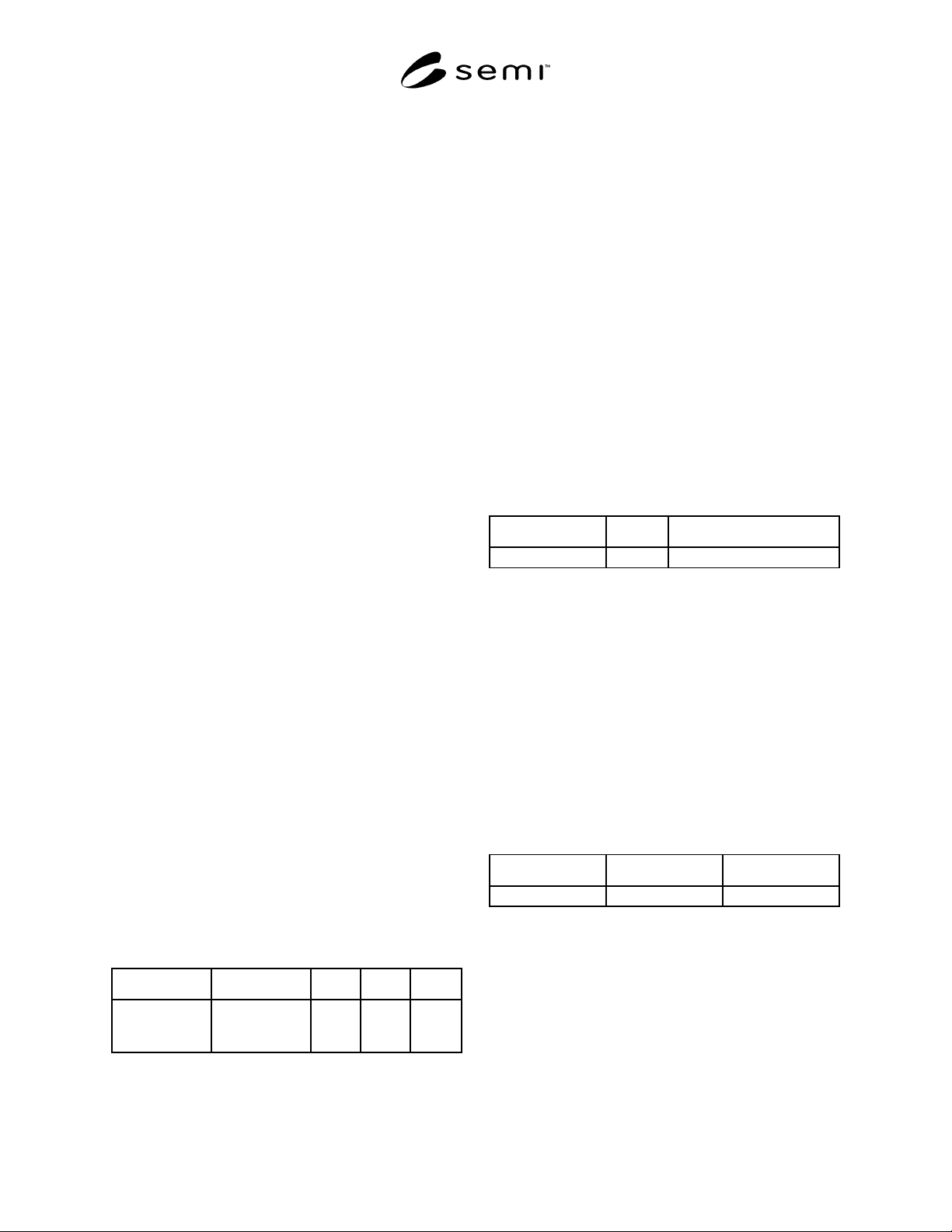
6.3 Object Attribute Representation — The object
information models for standardized objects will be
supported by an attribute definition table with the
following column headings:
Attribute Definition Access Rqmt Form
The formal text
name of the
attribute.
Description of
the information
contained.
RO or
RW
Y or N (see
below)
The access column uses RO (Read Only) or RW (Read
and Write) to indicate the access that users of Object
Services have to the attribute. Note that, in this
document, the access column is used only to indicate
user access via the network; no indication is made as to
local access as this level of specification is considered
to be implementation-specific. Thus, in the context of
this document, a RW attribute is a network-settable
attribute (i.e., an attribute whose value can be altered
from the network), while a RO attribute is a non-
network-settable attribute.
A ‘Y’ or ‘N’ in the requirement (Rqmt) column
indicates if this attribute must be supported in order to
meet fundamental compliance for the service.
The Form column is used to indicate the format of the
attribute.
6.4 Service Message Representation
6.4.1 Service Resource Definition — The service
resource definition table defines the specific set of
messages for a given service group, as shown in the
following table:
Service Type Description
Message name N or R The intent of the service.
Type can be either Notification (N) or Request (R).
Notification messages are initiated by the service
provider. No response is expected. Request messages
are initiated by the service user. Request messages ask
for data or for an operation to be performed. Request
messages expect a specific response (no presumption
on the message content).
6.4.2 Service Parameter Dictionary — Each parameter
should relate to either attributes from the object model
or events of the dynamic model (Harel State Chart). All
parameters to the services are listed in a single table or
dictionary. The column headings for this parameter
dictionary are as follows:
Parameter Form Description
Parameter X Data type A parameter
A row is provided in the table for each parameter of the
service. The first column contains the name of the
parameter. This is followed by columns describing the
form and the contents of the parameter.
The form column is used to indicate the type of data
contained in the parameter and the possible values it
may take on.
The description column describes the meaning of the
parameter and interrelationships with other parameters.