semi合集-English.pdf - 第2032页
SEMI E54.8-0305 © SEMI 1999, 2005 14 Table 17 Active Element ser vice mapping SEMI CDM Service ID Service Write Value to Index 64 nS4 Get Attribute Mapped as Read from Attribute Index nS5 Set Attribute Mapped as Write to…
SEMI E54.8-0305 © SEMI 1999, 2005 13
7.6 Services
7.6.1 DM Services
7.6.1.1 Get_Attribute and Set_Attribute are mapped to Read and Write services to the IM Objects.
7.6.1.2 The other services are mapped to a write at an UINT Object addressed with Index 96 as described in Table 3
and Table 15.
7.6.1.3 A read to Index 96 will return the last command executed successfully.
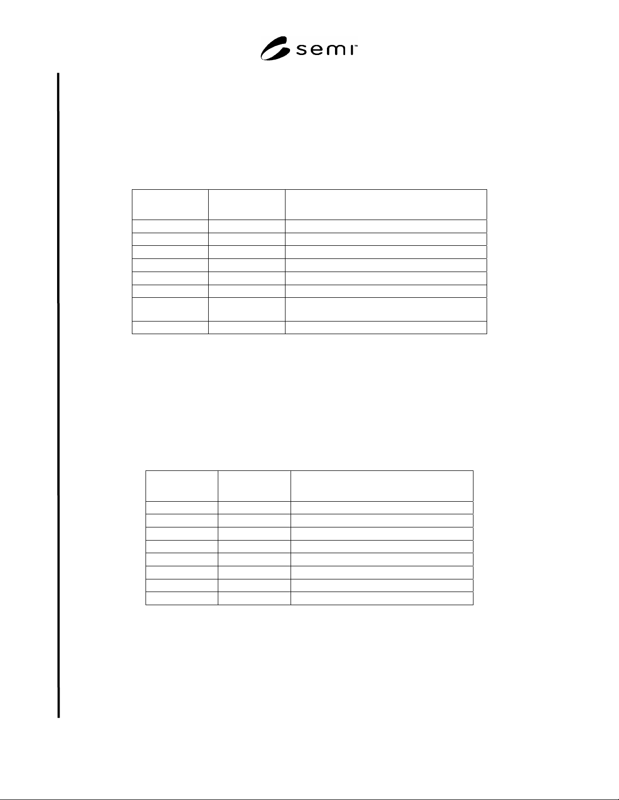
Table 15 DM Service Mapping
SEMI CDM Service
ID
Service Write Value to Index 96
DmS4 Get Attribute Mapped as Read from Attribute Index
DmS5 Set Attribute Mapped as Write to Attribute Index
DmS1 Reset 0
DmS2 Abort 1
DmS3 Recover 2
DmS6 Execute 3
DmS7 Perform
Diagnostics
4
DmS8 – DmS12 Optional Services are not mapped in PROFIBUS
7.6.2 SAC Services
7.6.2.1 Get_Attribute and Set_Attribute are mapped to Read and Write services with Slot and Index as described in
¶¶ 7.2 and 7.4.
7.6.2.2 The other services are mapped to a write at an UINT Object addressed with Index 64 as described in Table 3
and Table 16.
7.6.2.3 A read to Index 64 will return the last command executed successfully (Exception: Restore Default is not
mirrored).
Table 16 SAC Service Mapping
SEMI CDM
Service ID
Service Write Value to Index 64
SacS4 Get Attribute Mapped as Read from Attribute Index
SacS5 Set Attribute Mapped as Write to Attribute Index
SacS1 Reset 0
SacS2 Abort 1
SacS3 Recover 2
SacS6 Operate 3
SacS7 Restore Default 4
SacS8 Publish Attribute Optional Service not mapped in PROFIBUS
7.6.3 Active Element Services
7.6.3.1 Get_Attribute and Set_Attribute are mapped to Read and Write services with Slot and Index as described in
¶¶ 7.2 and 7.4.
7.6.3.2 The other services are mapped to a write at an UINT Object addressed with Index 64 as described in Table 2
and Table 17.
7.6.3.3 A read to Index 64 will return the last command executed successfully (Exception: Restore Default is not
mirrored).
SEMI E54.8-0305 © SEMI 1999, 2005 14
Table 17 Active Element service mapping
SEMI CDM Service ID Service Write Value to Index 64
nS4 Get Attribute Mapped as Read from Attribute Index
nS5 Set Attribute Mapped as Write to Attribute Index
nS1 Reset 0
nS2 Abort 1
nS3 Recover 2
nS6 Operate 3
nS7 Restore Default 4
7.7 PROFIBUS-DP Device Data Base
7.7.1 The specification of the Device Data Base (or GSD file) for a given SDM is beyond the scope of this
document. The PROFIBUS Trade Organization is responsible for the management of these files.
7.8 PROFIBUS-DP I/O Data Exchange
7.8.1 Input/Output attributes of the Application objects are communicated using the I/O Data Exchange method of
PROFIBUS-DP. This method is described in the PROFIBUS-DP standard. A list of which attributes are accessible
with this method is included in the PROFIBUS Device Profile for a given device type
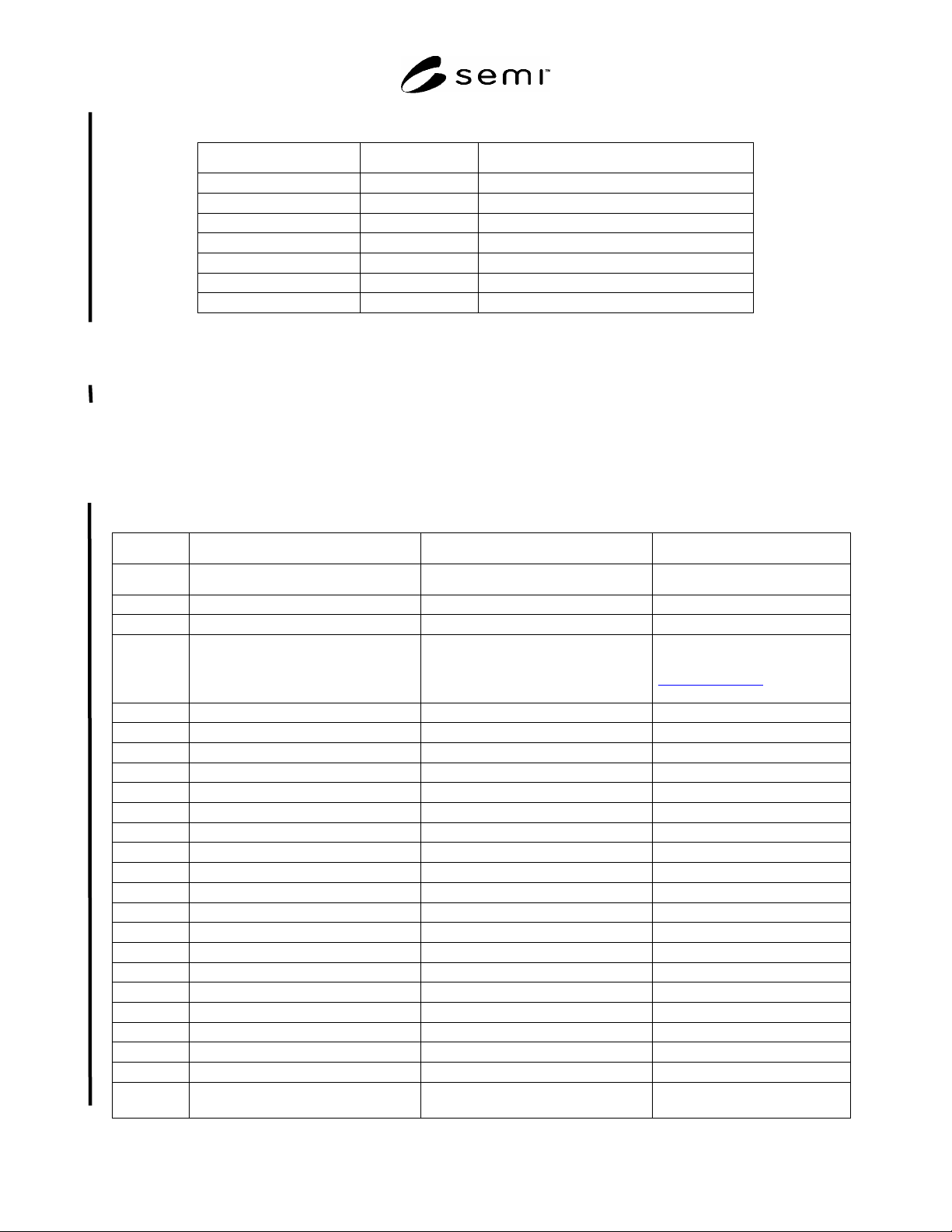
Table 18 DM Object Attribute Identifiers
SEMI CDM PROFIBUS Attribute Detail /Alternative Access Method
Attribute ID Attribute ID
DmA1 IM0, DEVICE_ID Device Type 8 Octets significant
DmA2 IM0, REVISION_COUNTER Standard Revision Level Shall be an UINT type
DmA3 IM0, MANUFACTURER_ID Device Manufacturer Identifier Shall be an UINT type, the
number is resolved via file from
www.profibus.com to supply with
web pages and phone numbers
DmA4 IM0, ORDER_ID Manufacturer Model Number
DmA5 IM0, SOFTWARE_REVISION Software or Firmware Revision Level
DmA6 IM0, HARDWARE_REVISION Hardware Revision Level
DmA7 IM0, SERIAL_NUMBER Serial Number 16 Octets maximum
DmA8 IM3 Device Configuration
DmA9 IM17, octet 10-11 Device Status Additional as Status Diagnosis
DmA10 IM16, octet 10-11 Reporting Mode
DmA11 IM16, octet 12-13 Exception Status Report Interval
DmA12 IM17, octet 12-13 Exception Status Additional as Status Diagnosis
DmA13 Slot 0 Index 0xe00b Exception Detail Alarm Additional as Channel Diagnosis
DmA14 Slot 0 Index 0xe00b Exception Detail Warning Additional as Channel Diagnosis
DmA15 Optional Attribute not mapped Visual Indicator N/A
DmA16 Context Alarm Enable Put in the SetPrm User Data
DmA17 Context Warning Enable Put in the SetPrm User Data
DmA18 Optional Attribute not mapped Exception Detail Type N/A
DmA19 Optional Attribute not mapped Exception Detail Alarm Queue N/A
DmA20 Optional Attribute not mapped Exception Detail Warning Queue N/A
DmA21 Optional Attribute not mapped Date and Time N/A
DmA22 Optional Attribute not mapped Date and Time Type N/A
DmA23–
DmA31
Reseved Reserved N/A

SEMI E54.8-0305 © SEMI 1999, 2005 15
8 Protocol Compliance
8.1 PROFIBUS International has established a qualified certification system, with test laboratories in Europe, Asia
and USA, which includes conformance testing and interoperability testing (address list can be found at
http://www.PROFIBUS.com/support.html). Certified products are listed with their certificate number in the
PROFIBUS Electronic Product Guide.
8.2 GSD files of all PROFIBUS-DP devices that are tested for their conformity to the PROFIBUS standard are
available in the GSD library on the World Wide Web Server of the PROFIBUS User Organization at
http://www.PROFIBUS.com.
9 Specific Device Model Mappings
9.1 Every type of device must have an identifier number. Vendors must apply for an identifier number from the
PROFIBUS User Organization for every Device Type. In order to receive a valid identifier number, a Device
Profile must be submitted in the form of a GSD File and Device Data Base Sheet.
9.2 The Device Profile must specify the identifiers for Objects, Attributes and Services for CDM and SDM
components, including data formats and bit mappings for specified parameters, as represented in this document.
9.3 The following sections specify mappings for Sensor Actuator Network Specific Device Models.
9.4 Mass Flow Device
9.4.1 Reference SEMI E54.3 for a complete specification of the SDM for Mass Flow Devices. Accordingly, the
following mapping rules apply to the identification tags for the Objects, Attributes and Services of this model.
9.4.2 Objects
9.4.2.1 Consistent with SEMI E54.3 and ¶7.4 above, the DM and SAC objects are identified as Object 1 and Object
2, respectively.
9.4.2.2 Notice that references for the Local Link Objects are not included; the existence of these objects are implied
by behavior and not explicitly included. Therefore, these objects are not accessible from the network.
9.4.2.3 Table 19 shows the mapping of the SDM.
9.4.2.4 Objects specified in SEMI E54.3 are listed under the heading NCS Module reference. Every instance is
allocated to a slot number. The configuration can be modeled in the GSD by using the Module reference as key for
the module description.
Table 19 Mass Flow Device Object Identifiers
SDM Object
Name
SDM Object ID NCS Module
reference
Sensor-AI-MF MFD3 103
Sensor-AI-AT MFD4 104
Assembly-MFM MFD5 105
Sensor-AI-Aux MFD6 106
Actuator-AO-MF MFD7 107
Controller MFD8 108
Local Link MFD9 109
SISO MFD10 110
SISO-Setpoint MFD11 111
Assembly-MFC MFD12 112
9.4.3 Attributes
9.4.3.1 The mapping of Attribute Tags and Identifiers is defined in §7 for SAC. The same method applies here for
the SDM.
9.4.3.2 Tables 20–24 show the mapping of the specific SDM attributes.