semi合集-English.pdf - 第2060页
SEMI E54.10-0600 © SEMI 2000 5 Attribute Name Attribute Identifier Access Network Req uired Form Leak Statu s A40 R No Byte, enumerated Tim e Stam p A41 RW No Date_A nd_Time Rese rved A42–A 64 — — Reserved f or SDM futur…
SEMI E54.10-0600 © SEMI 2000 4
8.1.7 General Requirements
8.1.7.1 Device Objects — All objects are defined in terms of their object name and Class/Object identifier.
Identifiers for all objects described in this document are summarized in Table 2.
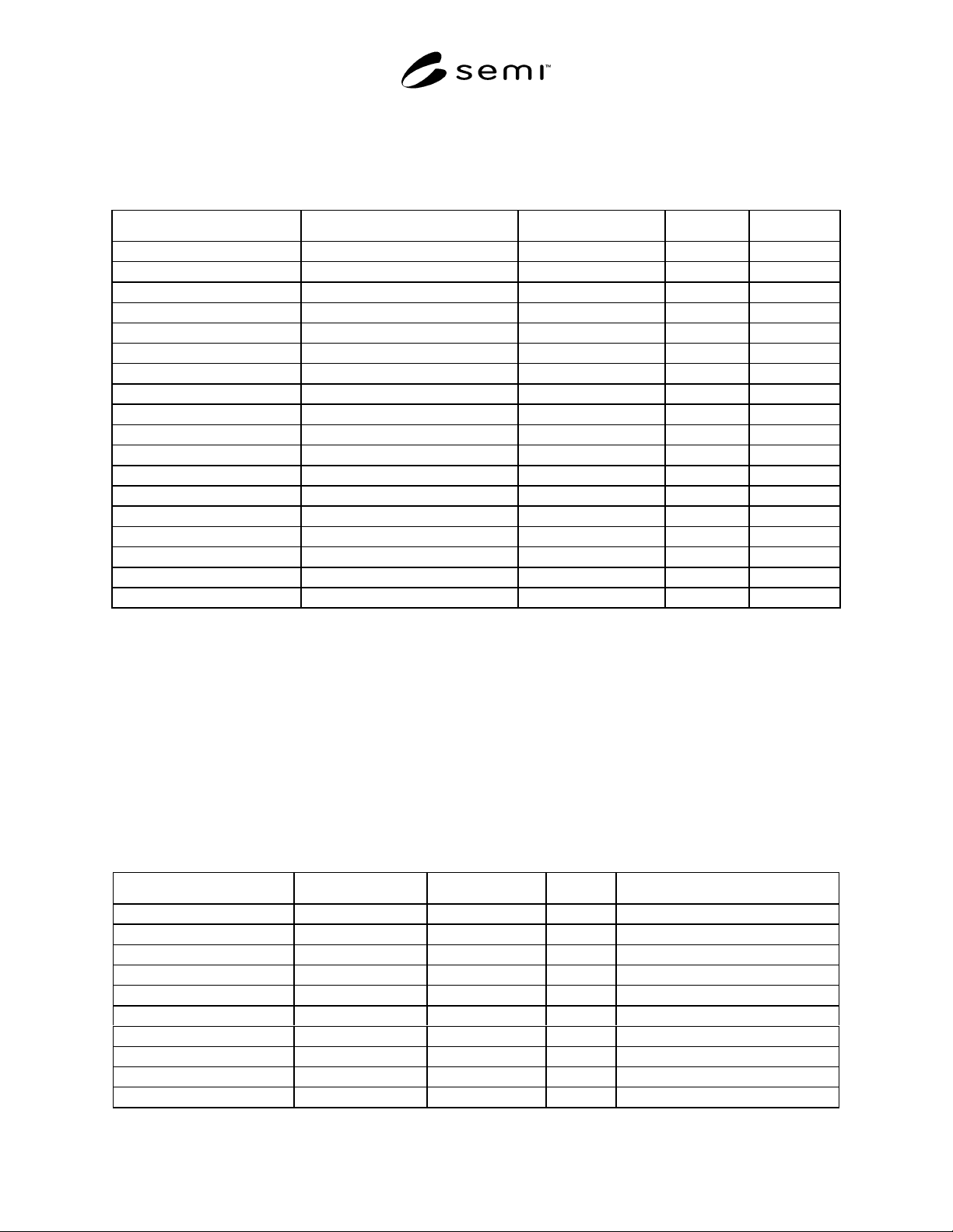
Table 2 In-Situ Particle Monitor Device Objects
Referenced Document Section Object Name Class/Object Identifier Minimum # Maximum #
8.2 Device Manager (DM) ISPMD1 1 1
8.3 Sensor Actuator Controller (SAC) ISPMD2 1 1
8.5 Sensor-AI-LCS ISPMD3 0 1
8.6 Sensor-AI-SLS ISPMD4 0 1
8.7 Sensor-AI-MNS ISPMD5 0 1
8.8 Sensor-AI-Counter ISPMD16 1 1024
8.9 Assembly-ISPM#1 ISPMD17 1 1
8.9 Assembly-ISPM#2 ISPMD18 0 1
8.9 Assembly-ISPM#3 ISPMD19 0 1
8.9 Assembly-ISPM#4 ISPMD20 0 1
8.9 Assembly-ISPM#5 ISPMD21 0 1
8.9 Assembly-ISPM#6 ISPMD22 1 1
8.9 Assembly-ISPM#7 ISPMD23 0 1
8.9 Assembly-ISPM#8 ISPMD24 0 1
8.9 Assembly-ISPM#9 ISPMD25 0 1
8.9 Assembly-ISPM#48 ISPMD64 0 1
— Reserved ISPM26–ISPM63 — —
— Manufacturer Specified > ISPM64 — —
8.1.7.2 Object Services — Not all object services listed in this document can necessarily be requested over the
network. They are included in this document because their behavior may generate network activity.
8.1.7.3 Object Behavior — For all service requests received over the network that are not supported by the object,
or contain a parameter value which is beyond the supported range, or which is otherwise invalid, a network specific
service error response is generated.
8.2 Device Manager Object (DM) — The Device Manager object is the device component responsible for
managing and consolidating the device operation as specified in SEMI E54.1 [3]. The following sections specify the
components of the DM object that are not specified in SEMI E54.1 or require further definition than specified in
SEMI E54.1.
8.2.1 Device Manager Object Attributes — Required and optional DM object attributes are listed in Table 3.
Table 3 DM Object Attributes
Attribute Name Attribute Identifier Access Network Required Form
Device Type A1 R Yes refer to CDM [1]
Exception Detail Alarm A13 R No refer to CDM [1]
Exception Detail Warning A14 R No refer to CDM [1]
Gain A33 RW * No REAL
Filter Bandwidth A34 RW * No REAL
Tool State A35 R No USINT, enumerated
Laser Status A36 R Yes USINT, enumerated
Flow Path A37 RW No USINT
Volume A38 R No REAL
Volume Units A39 R No Byte, enumerated
SEMI E54.10-0600 © SEMI 20005
Attribute Name Attribute Identifier Access Network Required Form
Leak Status A40 R No Byte, enumerated
Time Stamp A41 RW No Date_And_Time
Reserved A42–A64 — — Reserved for SDM future expansion
Manufacturer Specified > A64 — — Manufacturer Specific attributes
NOTE 1: “*” Indicates that the specific attribute is nonvolatile. Nonvolatile requires that the current attribute value be maintained through a
component power cycle.
8.2.1.1 Device Type — An attribute that uniquely
identifies the type of the device on the network. The
device type attribute is assigned as follows:
In-Situ Particle Monitor Device = “ISPM”
8.2.1.2 Exception Detail Alarm (Optional) — An
attribute which identifies the detailed alarm status of the
device. Table 4 defines the bit assignments associated
with the alarm exception detail.
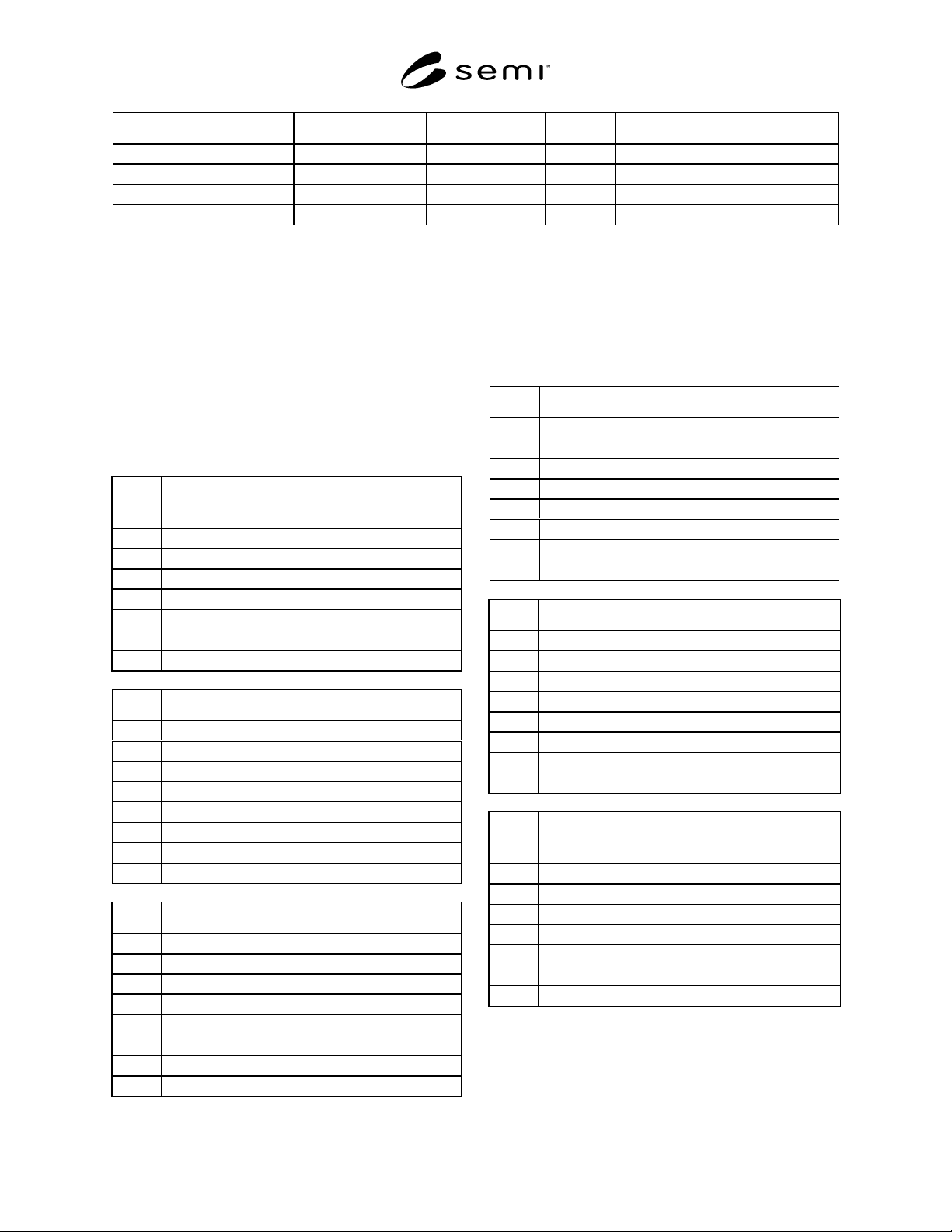
Table 4 Exception Detail Alarm Bit Assignments
Bit Device Specific Alarm[0]
0 Reserved
1 Interlock
2 Sensor Not Detected
3 Leak Detected
4 Reserved
5 Sensor Type Changed
6 Reserved
7 Reserved
Bit Device Specific Alarm[1]
0 High Laser Current
1High Stray Light
2 High Median Noise
3 High Calibration
4 High Fill Rate
5 High Flow Rate
6 Reserved
7 Reserved
Bit Device Specific Alarm[2]
0 Low Laser Current
1Low Stray Light
2 Low Median Noise
3 Low Calibration
4 Low Fill Rate
5 Low Flow Rate
6 Reserved
7 Reserved
8.2.1.3 Exception Detail Warning (Optional) — An
attribute which identifies the detailed warning status of
the device. Table 5 defines the bit assignments
associated with the warning exception detail.
Table 5 Exception Detail Warning Bit Assignments
Bit Device Specific Warning[0]
0Reserved
10
20
30
4Reserved
50
6Reserved
7Reserved
Bit Device Specific Warning[1]
0 High Laser Current
1High Stray Light
2 High Median Noise
3 High Calibration
4 High Fill Rate
5 High Flow Rate
6Reserved
7Reserved
Bit Device Specific Warning[2]
0 Low Laser Current
1Low Stray Light
2 Low Median Noise
3 Low Calibration
4 Low Fill Rate
5 Low Flow Rate
6Reserved
7Reserved
8.2.1.4 Manufacturer Exception Detail Size (Optional)
— An attribute that specifies the number of exception
detail bytes included in the alarm or warning details.

SEMI E54.10-0600 © SEMI 2000 6
8.2.1.5 Gain (Optional) — An attribute that specifies
the Gain value of the amplifier for the photodiode sig-
nal. The factory configured out-of-box value is deter-
mined by the manufacturer based on the sensor type.
8.2.1.6 Filter Bandwidth (Optional) — An attribute
that determines the bandwidth in kilohertz of the
amplifier for the photodiode signal. The factory
configured out-of-box value is determined by the
manufacturer based on the sensor type.
8.2.1.7 Tool State (Optional) — An attribute that
identifies the current state of the tool that is utilizing the
counter. In many cases, the ISPM device can detect and
report the Tool State; this variable is utilized for this
type of reporting. This attribute is enumerated and is
specified by the manufacturer.
8.2.1.8 Laser Status — An attribute that records the
current status of the laser. This attribute is enumerated.
The possible enumeration and the requirement for
support are as follows:
0 = LASER OFF (required)
1 = LASER TURNING ON (optional)
2 = LASER ON BUT NOT STABLE (optional)
3 = LASER ON AND STABLE (required)
4 = LASER INTERLOCKED (optional)
5 = SENSOR MISSING (required)
6–63 = Reserved
64–255 = Manufacturer Specified (optional)
8.2.1.9 Flow Path (Optional) — An attribute that
identifies the current flow path (from multiple sources)
being utilized. The source may be modified by a Host at
anytime. Changing the “Flow path” attribute connects
the ISPM device to a different source. When changing
sources, data is not valid for a time interval whose
length is a function of the distance to the source.
8.2.1.10 Volume (Optional) — An attribute that
maintains the sample volume. This attribute is used
primarily by liquid particle counters utilizing a
sampling technique in a small container to extrapolate
the particle count in the volume of interest. The value
of this attribute is the size of the small container.
8.2.1.11 Volume Units (Optional) — An attribute that
specifies the unit for the “Volume” attribute. This
attribute is enumerated and can take on one of the
following values: milliliters or gallons. (See Appendix
1 of SEMI E54.1 for assigned values.)
8.2.1.12 Leak Status (Optional) — An attribute that
indicates which one of the potential leak locations is
actually leaking. This attribute is enumerated and is
specified by the manufacturer. The enumerated value
corresponds to a specific leak location.
8.2.1.13 Time Stamp (Optional) — An attribute that
records the time when the last counting event
completed.
8.2.1.14 Duration (Optional) — An attribute that
defines the interval of time during which the particle
counts are collected and put into the bin assemblies.
8.2.1.15 Initial and Default Values
Table 6 DM Object Attribute Initial and Default Values
Attribute Initial Value Default Value Comment
Device Type ISPM ISPM ISPM = In-Situ Particle Monitor Device
Exception Detail Alarm 0 0
Exception Detail Warning 0 0
Laser Status 0 0 Laser Off