semi合集-English.pdf - 第21页
SEMI E1.9-0701 E2 © SEMI 1994, 2004 1 SEMI E1.9-0701 E2 MECHANICAL SPECIFICATION FOR CASSETTES USED TO TRANSPORT AND STORE 300 mm WAFERS This specification was technically approved by the Gl obal Ph ysical Interfaces &am…
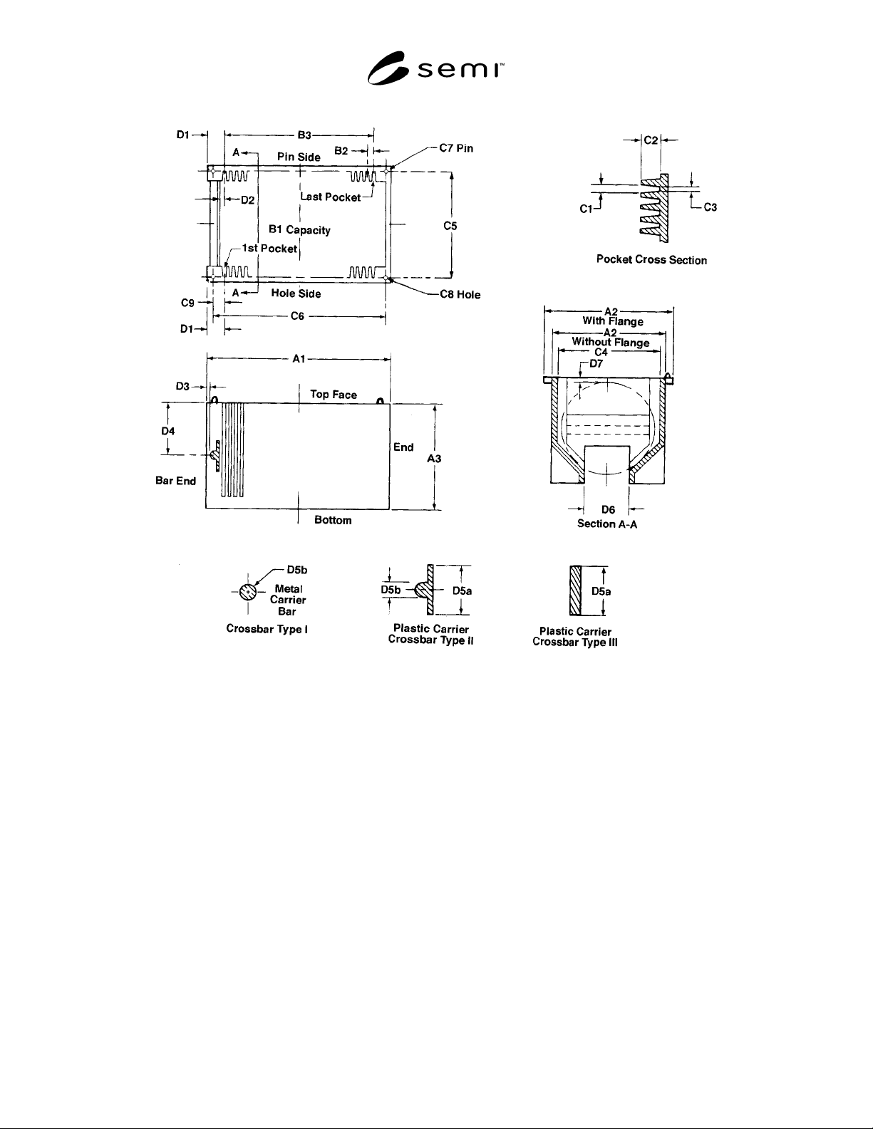
SEMI E1.5-91 © SEMI 1984, 2003 2
Figure 6
150 mm Plastic & Metal Wafer Carrier General Usage
NOTICE: SEMI makes no warranties or representations as to the suitability of the standards set forth herein for any
particular application. The determination of the suitability of the standard is solely the responsibility of the user.
Users are cautioned to refer to manufacturer’s instructions, product labels, product data sheets, and other relevant
literature respecting any materials mentioned herein. These standards are subject to change without notice.
The user’s attention is called to the possibility that compliance with this standard may require use of copyrighted
material or of an invention covered by patent rights. By publication of this standard, SEMI takes no position
respecting the validity of any patent rights or copyrights asserted in connection with any item mentioned in this
standard. Users of this standard are expressly advised that determination of any such patent rights or copyrights, and
the risk of infringement of such rights, are entirely their own responsibility.
Copyright by SEMI® (Semiconductor Equipment and Materials
International), 3081 Zanker Road, San Jose, CA 95134. Reproduction o
f
the contents in whole or in part is forbidden without express written
consent of SEMI.

SEMI E1.9-0701
E2
© SEMI 1994, 2004 1
SEMI E1.9-0701
E2
MECHANICAL SPECIFICATION FOR CASSETTES USED TO
TRANSPORT AND STORE 300 mm WAFERS
This specification was technically approved by the Global Physical Interfaces & Carriers Committee and is
the direct responsibility of the North American Physical Interfaces & Carriers Committee. Current edition
approved by the North American Regional Standards Committee on March 22 and April 30, 2001. Initially
available at www.semi.org May 2001; to be published July 2001. Originally published in 1994; previously
published June 1999.
E
This document was editorially modified in January 2003 to reflect the withdrawal of SEMI E44. Changes
were made to Sections 3.1, 4.2, 4.4, and 4.17. This document was also editorially modified in May 2004 to
reflect the withdrawal of SEMI E19.5. Changes were made to Section 7.1.
1 Purpose
1.1 This standard specifies the cassettes used to
transport and store 300 mm wafers in an IC
manufacturing facility. This includes both manual and
auto-transport use as well as high-speed extraction of
the wafers in processing equipment.
2 Scope
2.1 This standard is intended to set an appropriate level
of specification that places minimal limits on
innovation while ensuring modularity and
interchangeability at all mechanical interfaces. Most of
the requirements given in this specification are in the
form of maximum or minimum dimensions wit very
few required surfaces. Only the mechanical interfaces
for cassettes are specified; no materials requirements or
micro-contamination limits are given. However, this
standard has been written so that both metal and
injection-molded plastic cassettes can be manufactured
in conformance with it.
2.2 The cassette has the following components and
sub-components, and other features. A “† ” symbol
indicates components or features that include
dimensions required for boxes with non-removable
cassettes.
Key:
• Required feature
◊ Optional feature
• 1 top domain
• 2 optical wafer sensing paths
◊ 4 robotic handling flanges (optional)
◊ 1 top cassette identification tag area (optional)
• 2 or 4 side domains (2 in front and 2 in rear, if
needed)
• supports (for 13 or 25 wafers) with correct wafer
pitch (10 mm) †
• 1 optical cassette sensing hole on each front side
domain
◊ 1 side cassette identification tag area on front
right side domain only (optional)
◊ features that prevent wafer creep-out
(optional)
◊ 2 pentagonal side grip pits on each front side
domain (optional)
• 1 bottom domain
• 2 optical wafer sensing paths
• 5 carrier sensing pads †
• 4 info pads †
• 1 pod latch-pin hole
• 2 conveyor rails
• 2 fork-lift pick-up areas
• 2 fork-lift pin holes
• 3 features that mate with kinematic coupling pins
and provide a 10 mm lead in †
◊ 3 features that mate with kinematic coupling
pins and provide a 15 mm lead in (optional)
◊ 1 bottom cassette identification tag area
(optional)
• Other features
• multiple horizontal wafer sensing paths
• 2 end-effector exclusion zones †
3 Referenced Documents
3.1 SEMI Standards
SEMI E15 — Specification for Tool Load Port

SEMI E1.9-0701
E2
© SEMI 1994, 2004 2
SEMI E19 — Standard Mechanical Interface (SMIF)
SEMI E57 — Provisional Mechanical Specification for
Kinematic Couplings Used to Align and Support 300
mm Wafer Carriers
4 Terminology
4.1 bilateral datum plane — a vertical plane that
bisects the wafers and that is perpendicular to both the
horizontal and facial datum planes (as defined in SEMI
E57).
4.2 box — a protective portable container for a cassette
and/or substrate(s).
4.3 carrier capacity — the number of substrates that a
carrier holds.
4.4 cassette — an open structure that holds one or
more substrates.
4.5 cassette bottom domain — volume (below z6 above
the horizontal datum plane) that contains the bottom of
the cassette.
4.6 cassette sensing pads — surfaces on the bottom of
the cassette for triggering optical or mechanical sensors.
4.7 cassette side domains — volumes (from z6 above
the horizontal datum plane to z15 above the top
nominal wafer seating plane) that contain the mizo teeth
or slots that support the wafer and the supporting
columns on the sides and rear of the cassette.
4.8 cassette top domain — volume (higher than z15
above the top wafer) that contains the top of the
cassette.
4.9 conveyor rails — parallel edges on the bottom of
the cassette for supporting the cassette on roller
conveyors.
4.10 facial datum plane — a vertical plane that bisects
the wafers and that is parallel to the front side of the
carrier (where wafers are removed or inserted). On tool
load ports, it is also parallel to the load face plane
specified in SEMI E15 on the side of the tool where the
carrier is loaded and unloaded (as defined in SEMI
E57).
4.11 fork-lift slots — rectangular holes (open to the
front and rear) in the bottom of the cassette for picking
up the cassette with a fork.
4.12 front-opening unified pod (FOUP) — a box (that
complies with SEMI E47.1) with a non-removable
cassette (so that its interior complies with SEMI E1.9)
and with a front-opening interface (that mates with a
FIMS port that complies with SEMI E62) (as defined in
SEMI E47.1).
4.13 horizontal datum plane — a horizontal plane from
which projects the kinematic-coupling pins on which
the carrier sits. On tool load ports, it is at the load
height specified in SEMI E15 and might not be
physically realized as a surface (as defined in SEMI
E57).
4.14 nominal wafer center line — the line that is
defined by the intersection of the two vertical datum
planes (facial and bilateral) and that passes through the
nominal centers of the seated wafers (which must be
horizontal when the carrier is placed on the coupling)
(as defined in SEMI E57).
4.15 nominal wafer seating plane — horizontal plane
that bisects the wafer pick-up volume.
4.16 optical wafer sensing paths — lines of sight for
optically sensing the positions of the wafers. Several
horizontal optical wafer sensing paths are present in
between the cassette side domains. In addition, two
vertical optical wafer sensing paths are created by
rectangular exclusion zones in the front of the cassette
top and bottom.
4.17 pod — a box having a Standard Mechanical
Interface (SMIF) per SEMI E19.
4.18 process batch — a set of substrates that are
processed simultaneously in a process chamber.
4.19 robotic handling flanges — four horizontal
projections on top of the cassette for lifting and rotating
the cassette.
4.20 sensor hole — an indentation on the bottom of the
cassette for inserting optical sensors.
4.21 side grip pits — two rectangular indentations on
each side of the cassette for lifting and rotating the
cassette.
4.22 transport group — a set of substrates that are
transported together between tools.
4.23 virtual tracking unit — an entity (which could be
a number of substrates or an individual die or mask
group) that the factory floor control system treats as a
single unit for tracking purposes.
4.24 wafer carrier — any cassette, box, pod, or boat
that contains wafers (as defined in SEMI E15).
4.25 wafer extraction volume — the open space for
extracting a wafer from the cassette.
4.26 wafer pick-up volume — the space that contains
entire bottom of a wafer if the wafer has been pushed to
the rear of the cassette.
4.27 wafer set-down volume — the open space for
inserting and setting down a wafer in the cassette.