semi合集-English.pdf - 第2123页
SEMI E54.14-0305 © SEMI 2005 17 Table 19 Sensor AI-MF Object Attribute Identifiers SEMI SDM Attribute ID PROFINET Index Attribute A1 160 Flow Totalizer A2 161 Flow Hours A5 164 Zero Offset Mode A6 165 Zeroing Status A7 1…

SEMI E54.14-0305 © SEMI 2005 16
http://www.PROFIBUS.com/support.html
5
). Certified products are listed with their certificate number in the
Electronic Product Guide.
8.2 GSD files of all PROFINET devices that are tested for their conformity to the PROFIBUS standard are
available in the GSD library on the World Wide Web Server of the PROFIBUS User Organization at
http://www.PROFIBUS.com.
9 Specific Device Model Mappings
9.1 Every type of device shall have an identifier number. Vendors must apply for an identifier number from the
PROFIBUS User Organization. A Device Profile shall be submitted in the form of a GSD File and Device Data
Base Sheet.
9.2 The Device Profile must specify the identifiers for Objects, Attributes and Services for CDM and SDM
components, including data formats and bit mappings for specified parameters, as represented in this document.
9.3 The following sections specify mappings for Sensor Actuator Network Specific Device Models.
9.4 Mass Flow Device
9.4.1 Reference SEMI E54.3 for a complete specification of the SDM for Mass Flow Devices (MFD).
9.4.2 Objects
9.4.2.1 Consistent with SEMI E54.3 and ¶7.4 above, the DM and SAC objects are identified as Object 1 and Object
2, respectively.
9.4.2.2 Notice that references for the Local Link Objects are not included; the existence of these objects are implied
by behavior and not explicitly included. Therefore, these objects are not accessible from the network.
9.4.2.3 Table 18 shows the mapping of the SDM.
9.4.2.4 Objects specified in SEMI E54.3 are listed under the heading NCS Module ID. Every instance is allocated
to a slot number. The configuration can be modeled in the GSD by using the Module ID as key for the module
description.
Table 18 Mass Flow Device Object Identifiers
SDM Object
Name
SDM Object ID NCS Module ID
Sensor-AI-MF MFD3 103
Sensor-AI-AT MFD4 104
Assembly-MFM MFD5 105
Sensor-AI-Aux MFD6 106
Actuator-AO-MF MFD7 107
Controller MFD8 108
Local Link MFD9 109
SISO MFD10 110
SISO-Setpoint MFD11 111
Assembly-MFC MFD12 112
9.4.3 Attributes
9.4.3.1 The mapping of Attribute Tags and Identifiers is defined in §7 for SAC. The same method applies here for
the SDM.
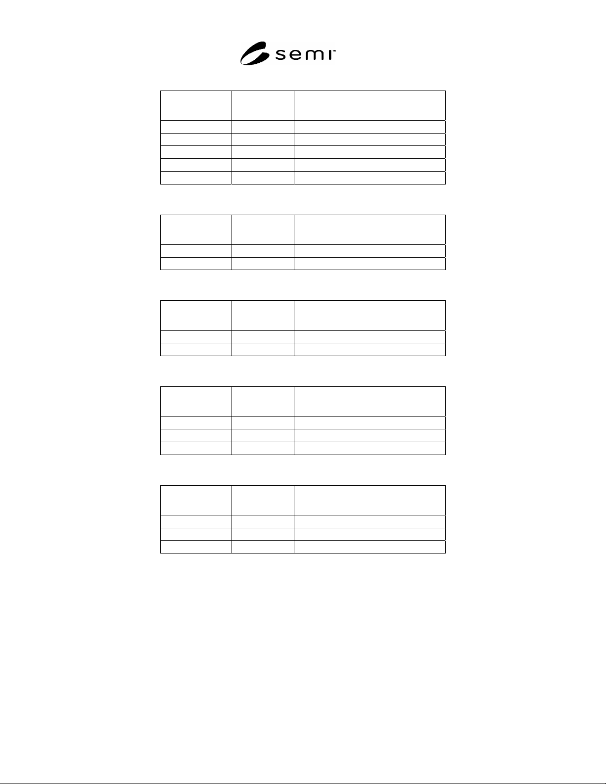
9.4.3.2 Tables 19–23 show the mapping of the specific SDM attributes.
5 Website maintained by PROFIBUS International.
SEMI E54.14-0305 © SEMI 2005 17
Table 19 Sensor AI-MF Object Attribute Identifiers
SEMI SDM
Attribute ID
PROFINET
Index
Attribute
A1 160 Flow Totalizer
A2 161 Flow Hours
A5 164 Zero Offset Mode
A6 165 Zeroing Status
A7 166 Autorange Status
Table 20 Actuator AO-MF Object Attribute Identifiers
SEMI SDM
Attribute ID
PROFINET
Index
Attribute
A1 160 Valve Type
A2 161 Override
Table 21 Controller Object Attribute Identifiers
SEMI SDM
Attribute ID
PROFINET
Index
Attribute
A1 160 Valve Type
A2 161 Override
Table 22 SISO Object Attribute Identifiers
SEMI SDM
Attribute ID
PROFINET
Index
Attribute
A1 65 Input
A2 66 Output
A3 67 Data Type
Table 23 SISO Setpoint Object Attribute Identifiers
SEMI SDM
Attribute ID
PROFINET
Index
Attribute
A33 97 Ramp Type
A34 98 Ramp Rate
A35 99 Ratio
9.4.4 Services
9.4.4.1 The mapping of Service Tags and Identifiers is defined in §7 for SAC. The same method applies here for
the SDM.
SEMI E54.14-0305 © SEMI 2005 18
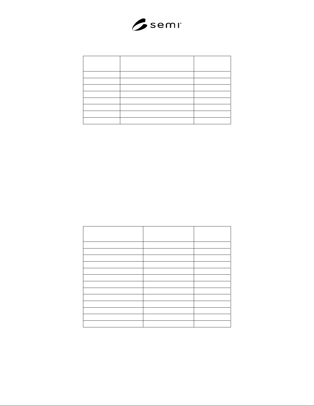
9.4.4.2 The additional Services of Sensor-AI-MF are mapped as described in Table 24.
Table 24 Sensor-AI-MF Additional Service Mapping
SEMI SDM Service
ID
Service Write Value to
Index 64
S1 Perform Zero Offset 11
S2 Query Supported Gas Type 12
S3 Select Programmed Gas Type 13
S4 Insert Gas Type 14
S5 Delete Gas Type 15
S6 Get Gas Calibration Data Value 16
S7 Set Gas Calibration Data Value 17
S8 Autorange 18
9.5 In-Situ Particle Monitor Device
9.5.1 Reference SEMI E54.10 for a complete specification of the SDM for In-Situ Particle Monitor Device (ISPM).
9.5.2 Objects
9.5.2.1 Consistent with SEMI E54.10 and ¶7.4 above, the DM and SAC objects are identified as Object 1 and
Object 2, respectively.
9.5.2.2 Notice that references for the Local Link Objects are not included; the existence of these objects are implied
by behavior and not explicitly included. Therefore, these objects are not accessible from the network.
9.5.2.3 Table 25 shows the mapping of the SDM.
9.5.2.4 Objects specified in SEMI E54.10 are listed under the heading NCS Module ID. Every instance is allocated
to a slot number. The configuration can be modeled in the GSD by using the Module ID as key for the module
description.
Table 25 In-Situ Particle Monitor Device Object Identifiers
SDM Object
Name
SDM Object ID NCS Module ID
Sensor-AI-LCS ISPMD03 203
Sensor-AI-SLS ISPMD04 204
Sensor-AI- MNS ISPMD05 205
Sensor-AI-Counter ISPMD16 216
Assembly-ISPM#1 ISPMD17 217
Assembly-ISPM#2 ISPMD18 218
Assembly-ISPM#3 ISPMD19 219
Assembly-ISPM#4 ISPMD20 220
Assembly-ISPM#5 ISPMD21 221
Assembly-ISPM#6 ISPMD22 222
Assembly-ISPM#7 ISPMD23 223
Assembly-ISPM#8 ISPMD24 224
Assembly-ISPM#9 ISPMD25 225
9.5.3 Attributes
9.5.3.1 The mapping of Attribute Tags and Identifiers is defined in §7 for SAC. The same method applies here for
the SDM.
9.5.3.2 Tables 26–31 show the mapping of the specific SDM attributes.