semi合集-English.pdf - 第215页
SEMI E28-92 © SEMI 1992, 2004 3 4.1.10 MFC calibration pressu re, inlet and outlet — the inlet and ou tlet pressure at which the MFC was calibrated (see Figure 2). 4.1.11 normal o perating press u re, inlet and outle t —…
SEMI E28-92 © SEMI 1992, 2004 2
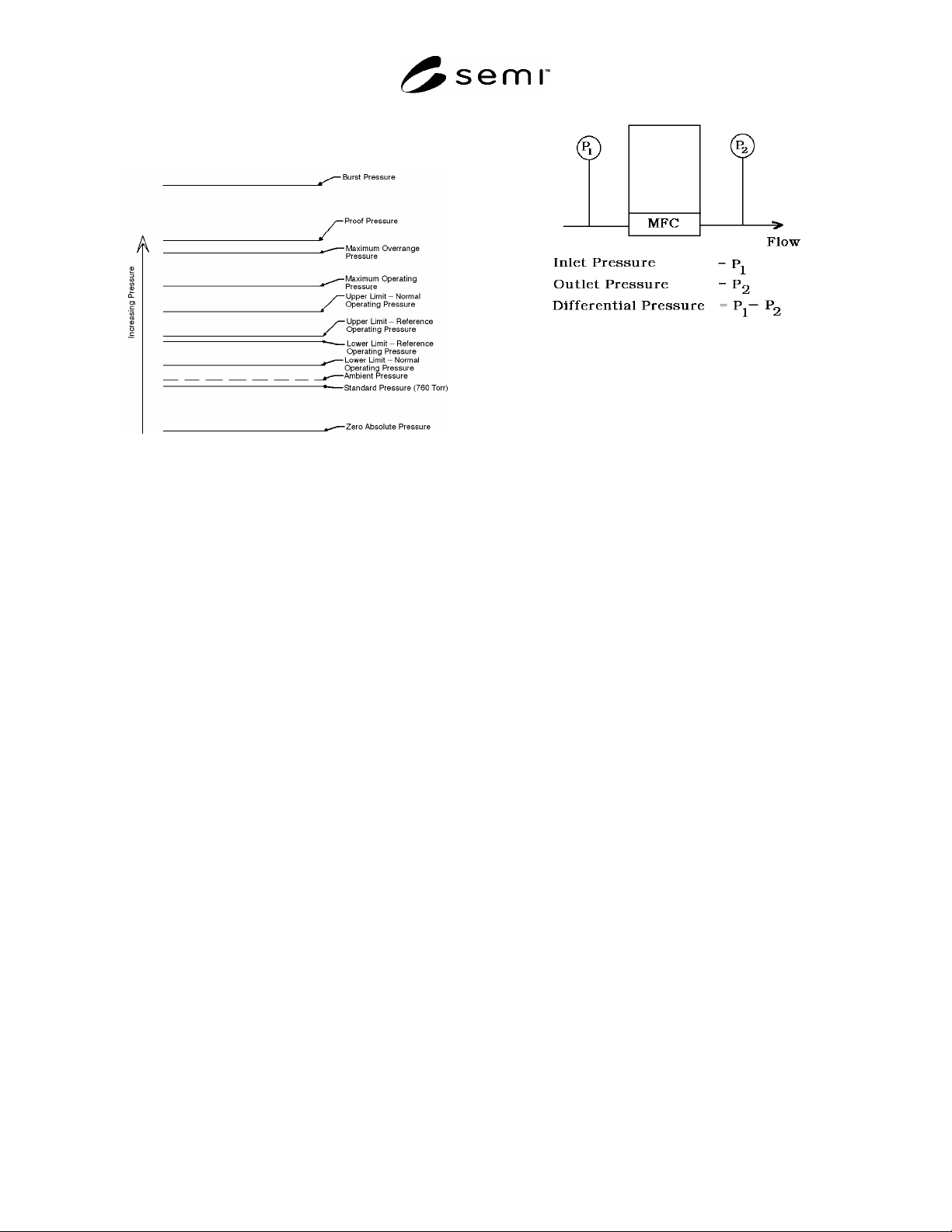
4.1.3 ambient pressure — the absolute pressure of the
medium surrounding the MFC (see Figure 2).
Figure 2
Pressure Definitions for MFCs
4.1.4 burst pressure — the gas pressure at which the
MFC may rupture.
4.1.5 differential pressure — the difference in absolute
pressure between two points of measurement in a
system (see Figure 3).
NOTE 3: To indicate unambiguously that a pressure
measurement is differential, the following abbreviations
should be used:
Pa (d) — Pascal, differential
psi (d) — Pounds per square inch, differential
Torr (d) — Torr, differential
kg/cm
2
(d) — Kilograms per square centimeter,
differential
B (d) — Bar, differential
4.1.5.1 Gauge pressures may also be used in the
differential pressure calculation if consistency is
maintained. A common error would be to take the
difference between an inlet gauge pressure and an outlet
absolute pressure without first converting to common
units.
4.1.5.2 As it applies to an MFC, differential pressure is
usually the measured difference in pressures between
the gas inlet and outlet fittings of the MFC.
Figure 3
Definition of Differential Pressure for MFCs
4.1.6 gauge pressure — the differential pressure
measured relative to ambient pressure. For example,
when the pressure within a system equals the prevailing
ambient pressure, the gauge pressure equals zero (see
Figure 1).
NOTE 4: To indicate unambiguously that a pressure
measurement is gauge, the following abbreviations should be
used:
Pa (g) — Pascal, gauge
psi (g) — Pounds per square inch, gauge
Torr (g) — Torr, gauge
kg/cm
2
— Kilograms per square centimeter, gauge
B (g) — Bar, gauge
NOTE 5: The performance of MFCs can vary significantly
with gas density. Atmospheric pressure varies with the
weather and altitude at various geographical locations. Gauge
pressure units commonly reference atmospheric pressure.
Therefore, the same gauge pressures measured at different
geographical locations may correspond to different gas
densities. For this reason, the use of gauge pressure units
with MFCs can be imprecise and should be avoided.
4.1.7 inlet pressure — the pressure at the inlet fitting
of the MFC (see Figure 3).
4.1.8 maximum operating pressure — operation is
permitted up to this inlet pressure, but performance is
not specified above normal operating pressure (see
Figure 2).
4.1.9 maximum overrange pressure — the maximum
gas pressure to which the MFC may be subjected
without degrading specified performance. When
returned to normal operating pressure, the MFC must
require no adjustment to return to specified
performance (see Figure 2).

SEMI E28-92 © SEMI 1992, 2004 3
4.1.10 MFC calibration pressure, inlet and outlet —
the inlet and outlet pressure at which the MFC was
calibrated (see Figure 2).
4.1.11 normal operating pressure, inlet and outlet —
the pressure range within which the MFC meets its
stated performance specifications (see Figure 2).
4.1.12 normal operating differential pressure — the
range of differential pressure (see Section 4.1.5)
required by the MFC to meet its stated performance
specifications.
NOTE 6: The upper and lower limits are dependent upon the
absolute inlet or outlet pressure. These limits are
manufacturer-specific.
4.1.13 outlet pressure — the pressure at the outlet
fitting of the MFC (see Figure 3).
NOTE 7: To completely specify the pressure operating
environment for MFCs, at least two of the following three
pressures must be listed: inlet, outlet, and differential.
4.1.14 proof pressure — the maximum gas pressure
the MFC may be subjected to without permanent
damage. Some adjustment may be necessary to make it
meet its specified performance when returning to
normal operating pressure. (see Figure 2.)
4.1.15 reference ambient — the composition and
pressure range of the ambient medium surrounding the
MFC within which performance specifications apply
without requiring correction for changes in the ambient
medium.
4.1.16 reference operating pressure, inlet and outlet —
the range of gas pressures on the inlet of the MFC and
across the MFC within which performance
specifications apply without requiring correction for gas
pressure effects (see Figure 2).
4.1.17 standard pressure — SEMI E12 defines
standard pressure as 760 Torr (101.32 kPa) (see Figure
2).
5 Gas Pressure Effects
5.1 Specified Gas — Gas pressure effects may be gas
species sensitive. The gas must be specified when
stating gas pressure effects. Nitrogen is recommended
as the standard gas.
5.2 Pressure Measurement Point — In this section,
pressure is assumed to be measured at the fitting of the
MFC, inlet or outlet, that is adjacent to the flow
transducer.
5.3 Total Calibration Effect — The change in output,
including zero and span, due to a change in gas pressure
from one normal operating pressure to a second normal
operating pressure. All other conditions must be held
within the limits of reference operating conditions.
5.4 Zero Calibration Effect — the change in zero due
to a change in gas pressure from one normal operating
pressure to a second normal operating pressure. All
other conditions must be held within the limits of
reference operating conditions.
5.4.1 The effect of gas pressure change on zero may be
expressed as a coefficient calculated as the ratio of full-
scale percent change in output to the corresponding
change in gas pressure. The change in gas pressure
should be specified. This coefficient is defined as the
“pressure coefficient of zero.”
5.4.1.1 Example — Pressure coefficient of zero may be
expressed as:
0.2% of full scale
240 kPa - 220 kPa
0.01% of full scale/kPa with N
2
NOTE 8: If the relation between gas pressure and change in
output is linear, one coefficient will suffice.
5.4.2 If the gas pressure influence is non-linear, a
different method of expression may be used. Two
examples:
5.4.2.1 The percent of full-scale change in output will
not exceed a specified value for any value of gas
pressure within a specified gas pressure range.
5.4.2.1.1 Example — “± 0.15% of full-scale maximum
error over 200 kPa to 250 kPa with N
2
”
5.4.2.2 It may be desirable to state a series of
coefficients for successive increments of gas pressure
within a specified gas pressure range.
5.5 Span Calibration Effect — The change in span due
to a change in gas pressure from one normal operating
pressure to a second normal operating pressure. All
other conditions must be held within the limits of
reference operating conditions.
5.5.1 The effect of gas pressure change on span may be
expressed as a coefficient calculated as the ratio of
percent of reading change in output to the
corresponding change in gas pressure. The change in
gas pressure should be specified. This coefficient is
defined as the “pressure coefficient of span.”

SEMI E28-92 © SEMI 1992, 2004 4
5.5.1.1 Example — Pressure coefficient of span may
be expressed as:
0.1% of reading
240 kPa - 220 kPa
0.005% of reading/kPa with N
2
NOTE 9: If the relation between gas pressure and change in
output is linear, one coefficient will suffice.
5.5.2 If the gas pressure influence is non-linear, a
different method of expression may be used. Two
examples:
5.5.2.1 The percent of span change in output will not
exceed a specified value for any value of gas pressure
within a specified pressure range of a particular gas.
5.5.2.1.1 Example — “± 0.1% of reading maximum
error over 200 kPa to 250 kPa with Nitrogen”
5.5.2.2 It may be desirable to state a series of
coefficients for successive increments of gas pressure
within a specified pressure range.
NOTICE: SEMI makes no warranties or
representations as to the suitability of the standards set
forth herein for any particular application. The
determination of the suitability of the standard is solely
the responsibility of the user. Users are cautioned to
refer to manufacturer's instructions, product labels,
product data sheets, and other relevant literature,
respecting any materials or equipment mentioned
herein. These standards are subject to change without
notice.
By publication of this standard, Semiconductor
Equipment and Materials International (SEMI) takes no
position respecting the validity of any patent rights or
copyrights asserted in connection with any items
mentioned in this standard. Users of this standard are
expressly advised that determination of any such patent
rights or copyrights, and the risk of infringement of
such rights are entirely their own responsibility.
Copyright by SEMI® (Semiconductor Equipment and Materials
International), 3081 Zanker Road, San Jose, CA 95134. Reproduction of
the contents in whole or in part is forbidden without express written
consent of SEMI.