semi合集-English.pdf - 第220页
SEMI E31-93 © SEM I 1993 2 4 Electrical Connectors (sh o w n as r eceptacle) Note: Direct term inal connections a re used f or most f ixed fac ilities and loads, which re quire higher curre nt than the value speci fie d …
SEMI E31-93 © SEMI 19931
SEMI E31-93
SPECIFICATION FOR ELECTRICAL INTERFACE, JAPAN ONLY
NOTE: For U.S. electrical interface requirements, see SEMI E7.
1 Introduction
1.1 Purpose — The purpose of this standard is to
ensure common electrical interfaces that fulfill the
requirements of equipment suppliers and users in the
Japan region and to ease the design and functionality of
semiconductor equipment manufacturing facilities in
the future.
1.2 Scope — This standard recommends electrical
interfaces for selected power supplies as follows:
— Facilities-Systems Motors and electrical loads
having various voltages, currents, and phases
— Electrical connectors
— Cords/cables
2 Referenced Documents
2.1 JIS-C-8303 — Japanese Industrial Standard
1
2.2 JCS 168C-73 — Japanese Cable Standard
2
JEAC-78 — Japanese Electrical Association
Committee
3
3 Facilities
3.1 Motor
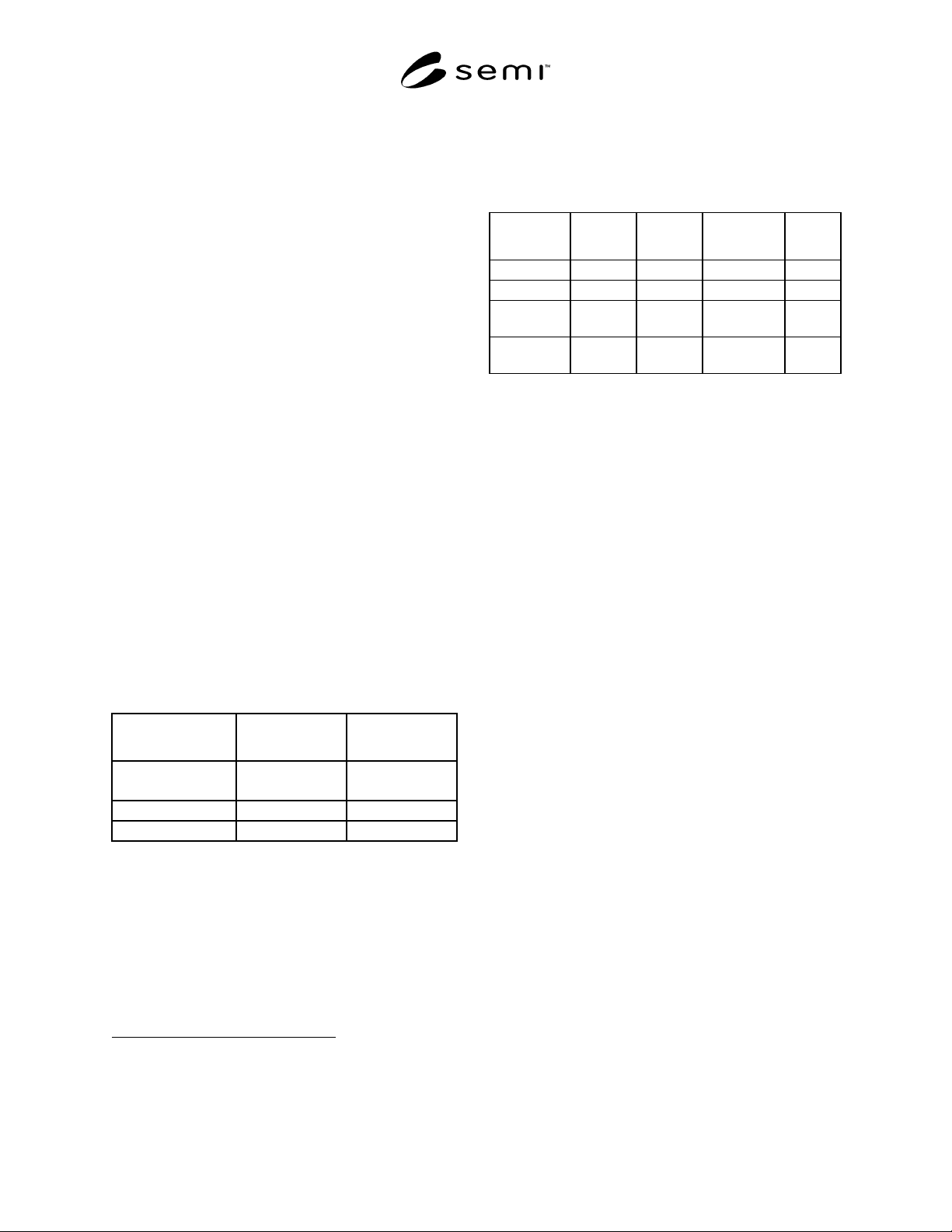
Power (W) Phase/Voltage
JEAC-78 Specified
Current (A)
35 to 400 1P 100 V
1P 200 V
2.2 to 9.5
1.1 to 4.4
200 to 3700 3P 200 V 1.8 to 17.4
200 to 7500 3P 400 V 0.9 to 17
Note: Specified currents are 0.9 times each current,
respectively, in the case of 110 V/220 V/440 V. Direct current
motors are excluded.
3.2 Voltage, Current, and Phase of Electrical Loads
(for calculation)
1 Japan Standard Association, 4-1-24 Akasaka, Minato-ku, Tokyo
2 Japan Cable Industry Association, 1-12-22 Tsukiji, Chuo-ku, Tokyo
3 Japan Electrical Association, 1-7-1 Yurakucho, Chiyoda-ku, Tokyo
Power (W) 1P 100V 1P 200V 3P 200V
JEAC-78
3P 400V
0 to 3000 0 to 30A 0 to 15A 0 to 8.7A
3000 to 5000 15 to 25A 8.7 to 14.5A
5000 to
30000
14.5 to 87A
30000 or
more
88A or more 44A or
more
Note: Specified currents are 0.9 times each current
respectively, in the case of 110V/220V/440V.
SEMI E31-93 © SEMI 1993 2
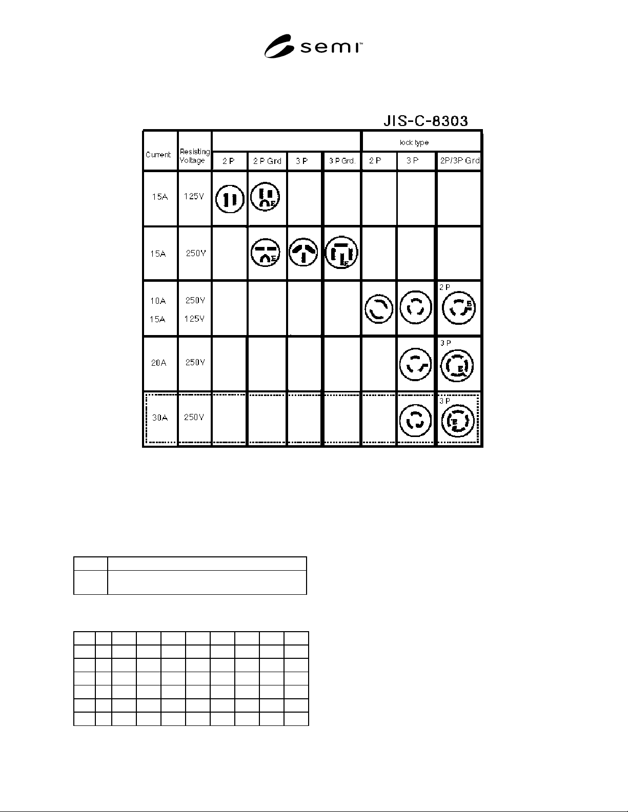
4 Electrical Connectors (sh own as receptacle)
Note: Direct terminal connections are used for most fixed facilities and loads, which require higher current than the value
specified above. 30A/250V shows at reference which is specified by the NEMA standards L6-30R and L15-30R.
5 Cable Current Tolerances
Key:
VV Vinyl insulation, vinyl sheathed cable
CV Construction polyethylene insulation, vinyl sheathed
cable
JCS 168C-73 Unit (A)
1.0Ø 2.0Ø 2sq 3.5sq 5.5sq 8sq 14sq 22sq
VV*1114192838476791
** 10 12 18 25 33 42 60 79
*** 9 10 15 22 29 37 53 70
CV*162333465974105135
** 17 20 28 40 52 66 94 125
***14172434455679105
* Single Conductor Three Cables
** Twin Conductors One Cable
*** Three Conductors One Cable
Note: The above specification is for cable in conduit in air.
Current tolerance of CV is different than that of VV due to the
difference in temperature tolerances (VV/60°C and
CV/90°C).
Ø: Diameter of Conductor (mm)
Sq: Cross-Sectional Area of Conductor (mm2)
SEMI E31-93 © SEMI 19933
APPENDIX
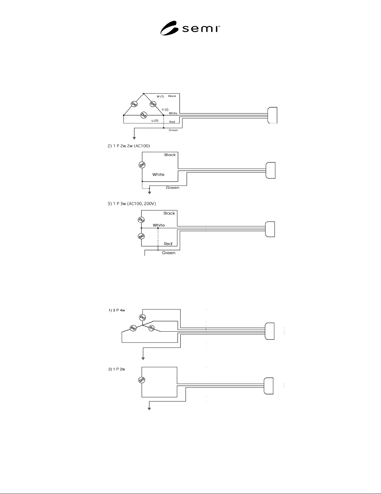
Examples of Wire Connection of Power Supply in Japan
Examples of Wire Connection of Power Supply in United States (Reference)
Notes: White wire connected at the grounded side. [White is also used for a neutral line (grounded side) in the U.S.] A single green wire other
than a cable is typically used for ground. In the case of a single wire, sometimes a black wire is substituted for blue. - - - - indicates that the wires
are normally grounded, with some exceptions. There are no special rules regarding colors of wires except a wire used for ground (green).
However, the figure shows common examples in Japan.