semi合集-English.pdf - 第2225页
SEMI E58-0703 © SEMI 1997, 2003 6 4.2.18 symptom — A user-detected event (e.g., smoke observed). 4.2.19 timestamp — The notation of the date and time of the occurrence of an event [SEMI E 42]. 4.2.20 timestamp format — A…
SEMI E58-0703 © SEMI 1997, 2003 5
3.2 Other Document
Harel, D., “Statecharts: A Visual Formalism for
Complex Systems,” Science of Computer Programming
8 (1987) 231–274
NOTE 1: As listed or revised, all documents cited shall be
the latest publications of adopted standards.
4 Terminology
4.1 Acronyms — The following acronyms are used in
this document.
4.1.1 ARAMS — Automated Reliability, Availability,
and Maintainability Standard, as defined by this
document.
4.1.2 CTMC — Cluster Tool Module Communications
[SEMI E38].
4.1.3 EMS — Exception Management Standard [SEMI
E41].
4.1.4 ERS — Event Reporting Standard [SEMI E53].
4.1.5 GEM — Generic Equipment Model [SEMI E30].
4.1.6 OSS — Object Services Standard [SEMI E39].
4.1.7 RAM — Reliability, Availability, and
Maintainability.
4.2 General Terms — The following definitions for
general terms are used in this document. References are
given in brackets.
4.2.1 alarm — Related to any abnormal situation on the
equipment that may endanger people, equipment, or
material being processed [SEMI E30, SEMI E41].
4.2.2 collection event — An event (or grouping of
related events) on the equipment that is considered to
be significant to the host [SEMI E30].
NOTE 2: A state transition in a formal state model always
represents a collection event unless explicitly stated
otherwise.
4.2.3 equipment production criteria — The set of
conditions and operating specifications that must be
satisfied for the equipment to consider itself as
performing its intended function. This includes basic
requirements for information, material to process, and
the absence of any detectable exception conditions
(e.g., no alarms). It also includes criteria specific to the
equipment model, such as a required level for vacuum
pressure and availability of consumables and support
tools required for its process.
4.2.4 event — A detectable occurrence significant to
the equipment.
NOTE 3: Within the context of ARAMS, an event may be
detected by either the equipment or the user.
4.2.5 event report — A message the equipment sends
to the host on the occurrence of a collection event.
4.2.6 exception — An alarm or error that is reported to
the user and that may or may not be recoverable.
4.2.7 fault — An exception.
4.2.8 host — The intelligent system that communicates
with the equipment, acts as a supervisory agent, and
represents the factory and the user to the equipment.
4.2.9 intended function — A manufacturing function
that the equipment was built to perform. This includes
transport functions for transport equipment and
measurement functions for metrology equipment as
well as process functions such as physical vapor
deposition and wire bonding. Complex equipment may
have more than one intended function.
4.2.10 interrupt (interruption) — A failure [SEMI
E10].
4.2.11 operator — Any person who communicates
locally with the equipment through the equipment’s
control panel.
4.2.12 state — A static set of conditions and associated
behavior. While all of its conditions are met, the state is
current (active). Behavior within a given state includes
the response to various stimuli.
NOTE 4: Within the scope of this document, the term “state”
generally refers to one of the six equipment states defined by
SEMI E10 and used in the ARAMS State Model: productive,
standby, engineering, scheduled downtime, unscheduled
downtime, and non-scheduled time.
4.2.13 state model — A collection of states and state
transitions that combine to describe the behavior of a
system. This model includes a definition of the
conditions that delineate a state, the activities possible
within a state, the events that trigger transitions to other
states, and the process of transitioning between states.
4.2.14 state transition — A change from one state to
another state.
4.2.15 standby condition — Any condition during
manufacturing time when the equipment’s production
criteria are not satisfied, and it is fault free and
otherwise able to perform its intended function.
4.2.16 substate — A refinement of a state.
NOTE 5: States may be subdivided into substates to facilitate
more concise definition of behavior. Thus, a hierarchy is
defined whereby any state may be a substate of some parent
state and in turn be the parent of its own substates [SEMI
E30, Appendix].
4.2.17 superstate — The parent state of two or more
states.
SEMI E58-0703 © SEMI 1997, 2003
6
4.2.18 symptom — A user-detected event (e.g., smoke
observed).
4.2.19 timestamp — The notation of the date and time
of the occurrence of an event [SEMI E42].
4.2.20 timestamp format — A text string of the form
“YYYYMMDDhhmmsscc”, where:
YYYY = year (e.g., 1995)
MM = month (01–12)
DD = day (01–31)
hh = hour (00–23)
mm = minute (00–59)
ss = second (00–59)
cc = centisecond (00–99)
4.2.21 trigger — An event that causes a change in the
state of the equipment. Examples are changes in sensor
readings, alarms, messages received from the host, and
operator commands.
4.2.22 user — Any entity interacting with the
equipment, either locally as an operator or remotely via
the host. From the equipment’s viewpoint, both the
operator and the host represent the user.
4.3 data types — The following terms are used to
represent valid types of data.
4.3.1 form — Type of data: positive integer, unsigned
integer, integer, floating point (float) enumerated,
Boolean, text, formatted text, structure, list, ordered list.
4.3.2 positive integer — May take the value of any
positive whole number. Messaging protocol may
impose a limit on the range of possible values.
4.3.3 unsigned integer — May take the value of any
positive integer or zero. Messaging protocol may
impose a limit on the range of possible values.
4.3.4 integer — May take on the value of any negative
or unsigned integer. Messaging protocol may impose a
limit on the range of possible values.
4.3.5 floating point (float) — May take on any single
(real) numeric value, positive or negative. Messaging
protocol may impose a limit on the range of possible
values.
4.3.6 enumerated — May take on one of a limited set
of possible values. These values may be given logical
names, but they may be represented by any single-item
data type.
4.3.7 boolean — May take on one of two possible
values, equating to TRUE and FALSE.
4.3.8 text — A character string. Messaging protocol
may impose restrictions, such as length or ASCII
representation.
4.3.9 formatted text — A character string with an
imposed format. This could be by position, by use of
special characters, or both.
4.3.10 structure — A specific set of items, of possibly
mixed data types, in a specified arrangement.
4.3.11 list — A set of one or more items that are all of
the same form (one of the above forms).
4.3.12 ordered list — A set of items in specific
sequence.
5 Basic Requirements
1.5 An ARAMS-compliant implementation requires
provision of certain capabilities defined by other
standards: accessibility to status information, event
reporting, alarm management, and provision of an
internal time-and-date clock. These requirements may
be satisfied through compliance to one of the following
sets of requirements:
• The Generic Equipment Model (GEM):
• Clock Services
• Event Notification
• Status Data Collection
• Equipment Constants
• Alarm Management
• The following set of standards:
• Object Services Standard
• Clock Services, Cluster Tool Module
Communications
• Event Reporting Standard
• Exception Management Standard
1.6 The developer is expected to be familiar with the
appropriate documents before attempting to implement
ARAMS (see Section 16.1).
6 Conventions
This document follows the conventions for state model
methodology and service definitions used by the SEMI
standards referenced in Section 3.
6.1 State Model Methodology — This document uses
the state model methodology in SEMI E30 to describe
the behavior of equipment. A state model has three
elements: definitions of each state and substate, a
SEMI E58-0703 © SEMI 1997, 2003 7
diagram of the states and the transitions between states,
and a state transition table. The diagram of the state
model uses the Harel State Chart notation. An overview
of this notation is presented in an appendix of SEMI
E30. The formal definition of this notation is presented
in Science of Computer Programming 8, “Statecharts:
A Visual Formalism for Complex Systems”, by D.
Harel, 1987.
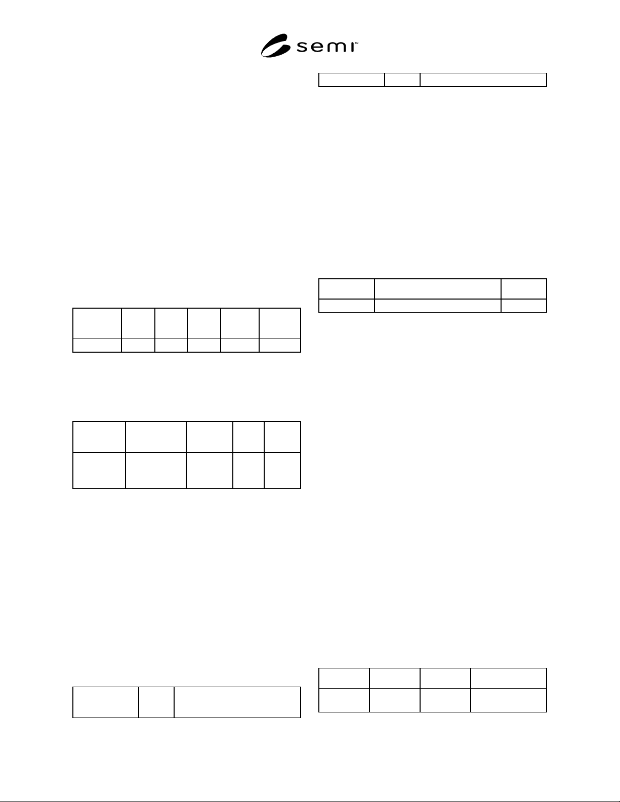
1.6.1 Transition tables are provided in conjunction
with the state diagrams to explicitly describe the nature
of each state transition. A transition table contains
columns for Transition #, Current State, Trigger, New
State, Action(s), and Comment. The “trigger” (column
3) for the transition occurs while in the “current” state.
The “actions” (column 5) includes a combination of 1)
actions taken upon exit of the current state, 2) actions
taken upon entry of the new state, and 3) actions taken
which are most closely associated with the transition.
No differentiation is made between these cases.
#
Current
State
Trigger
New
State
Action(s)
Comment
Transition #
1.7 Object Attribute Representation — The object
information models for standardized objects will be
supported by an attribute definition table with the
following column headings:
Attribute
Name
Definition
Access
Reqd
Form
The formal
text name of
the attribute.
Description of
the information
contained.
RO or RW Y or N (see
below)
1.7.1 The Access column uses RO (Read Only) or RW
(Read and Write) to indicate the access that users of the
service have to the attribute.
1.7.2 A ‘Y’ or ‘N’ in the Required (Reqd) column
indicates if this attribute must be supported in order to
meet fundamental compliance for the service.
1.7.3 The Form column is used to indicate the format
of the attribute (see Section 4 for definitions).
6.2 Service Message Representation
1.7.4 Service Resource Definition — A service
definition table defines the specific set of messages for
a given service resource, as shown in the following
table:
Message
Service Name
Type
Description
Message name N or R The intent of the service
1.7.4.1 Type can be either N = Notification or R =
Request.
1.7.4.2 Notification type messages are initiated by the
service provider and the provider does not expect to get
a response from the service user (consumer/subscriber).
1.7.4.3 Request messages are initiated by a service
user. Request messages ask for data or an activity from
the provider. Request messages expect a specific
response message (no presumption on the message
content).
1.7.5 Service Parameter Dictionary — A service
parameter dictionary table defines the parameters for
one or more services, as shown in the following table:
Parameter Description Form
Parameter X A parameter called X is B in A. Data type.
1.7.5.1 A row is provided in the table for each
parameter of the service. The first column contains the
name of the parameter. This is followed by columns
describing the form and contents of the corresponding
parameter.
1.7.5.2 The Form column is used to indicate the type
of data contained in a parameter (see Section 4 for
definitions).
1.7.5.3 The Description column in the Service
Parameter Dictionary table describes the meaning of the
parameter, the allowed values, and any
interrelationships with other parameters.
1.7.5.4 To prevent the definition of numerous
parameters named “XxxList”, this document adopts the
convention of referring to the list as “(List of) Xxx”. In
this case, the definition of the variable Xxx will be
given, not of the list. The term “list” indicates a
collection (or set) of zero or more items of the same
data type.
1.7.5.5 Where a list is used in both the request and the
response, the list order in the request is retained in the
response. A list must contain at least one element unless
zero elements are specifically allowed.
1.7.6 Service Message Definition — A service
message definition table defines the parameters used
in a service, as shown in the following table:
Parameter Req/Ind Rsp/Conf Description
Parameter X (see below) (see below) A description of the
parameter.