semi合集-English.pdf - 第2508页
SEMI E88-1104 E © SEMI 1999, 2004 5 6.13 Transfer Completed Port OP LP2 LP1 BP PGV, AGV, OHV Access ible Stoc ker Cr ane Acc essi ble Stoc ker Ins ide Stoc ker Ou tsi de OP LP BP Stocker Crane Accessible Stoc ker Ins ide…

SEMI E88-1104
E
© SEMI 1999, 2004 4
6.1.2 Output to the Interbay Output Port
6.1.2.1 The destination for a transfer command to
move a carrier to an interbay output port must be a
loading port. It is the responsibility of the Host to
ensure that sufficient capacity exists in the destination
stocker when delivering from a source stocker to a
destination stocker (i.e., an interbay move). For
example, it would be the responsibility of the Host to
check the remaining capacity of the destination stocker
prior to issuing the transfer command to send the carrier
to the interbay output port of the source stocker.
6.1.3 Output to the Intrabay Output Port
6.1.3.1 The destination for a transfer command to
move a carrier to an intrabay output port must be a
loading port.
6.1.4 Store to the Stocker Shelf
6.1.4.1 The specific stocker shelf location is to be
controlled by the Stocker Controller (SC). The Host
does not specify a shelf ID in a transfer command. The
Host sends the name of a zone as the destination in the
transfer command
6.1.4.2 The carrier is stored to a stocker shelf
temporarily when the Host requested output port
destination is occupied. This is the responsibility of the
Stocker Controller. The carrier count of the stocker is
incremented due to this temporary storage (i.e., the
current capacity decreases).
6.1.4.3 For multi-crane stockers, the carrier is
temporarily stored to a stocker shelf when the source
and destination is not accessible by the same stocker
crane. This is the responsibility of the Stocker
Controller. The carrier count of the zone containing the
location where the carrier is temporarily stored is
incremented due to this temporary storage (i.e. the
current capacity decreases).
6.2 Quantity Control in the Stocker (Capacity
Planning)
6.2.1 The number of carriers in the stocker is
controlled by the Host. A list of carrier database entries
in the specified stocker’s SC database will be available
to the Host upon request via a remote command.
6.3 Number of Stocker Cranes
6.3.1 No Limitation. May be zero for systems that do
not include a crane. Host does not control the stocker
crane directly.
6.4 Port Type
6.4.1 The independent input port and the independent
output port are required for the Stocker SEM. The
swapping type is considered as an independent port.
6.5 Plural Sets of Input/Output Ports
6.5.1 Plural sets of Input/Output ports connected to the
interbay or intrabay transport system must be
considered. (This would be considered a Multi-loop
type interface connection to the stocker.) Examples of
plural sets of interfaces are as follows:
Main Loop/Sub Loop,
Right-handed rotation/Left-handed rotation, and
Double Track (i.e., Stacked Track).
6.6 Carrier ID Reader
Manual Input Port: Carrier ID Reader is
mandatory.
Automated Input Port: Carrier ID Reader is a
customer option.
Carrier ID Reader at any output port: Carrier ID
Reader is a customer option.
6.6.1 The intrabay automated input port is sometimes
used as the manual Input Port. If one port is used for
both an automated and a manual, the Carrier ID Reader
is mandatory for this port. If there is a Carrier ID
Reader, the scenario for a stocker transfer without a
Carrier ID Reader is not applicable.
6.7 Tag
6.7.1 Same assumptions as Carrier ID Reader.
6.8 Carrier Exchanger/Gas Purger
6.8.1 Out of scope of Stocker SEM.
6.9 Robot Arm in the Passive Type Stocker
6.9.1 No assumption is made regarding the passive
type stocker.
6.10 Empty or Not Empty Carriers
6.10.1 No assumption is made regarding empty and not
empty carriers.
6.11 Monitor/Dummy
6.11.1 No assumption.
6.12 Operation Mode
6.12.1 No assumption.
SEMI E88-1104
E
© SEMI 1999, 2004 5
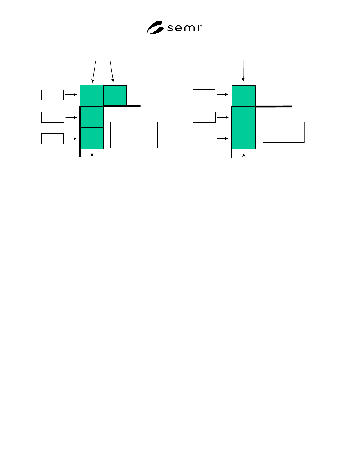
6.13 Transfer Completed Port
OP
LP2
LP1
BP
PGV, AGV, OHV Accessible
Stocker Crane Accessible
Stocker Inside
Stocker Outside
OP
LP
BP
Stocker Crane Accessible
Stocker Inside
Stocker Outside
PGV, AGV, OHV Accessible
OP - ouput port
BP - buffer port
LP1 - loading port 1
LP2 - loading port 2
OP - ouput port
BP - buffer port
LP - loading port
Case 3
Case 2
Case 1
Case 3
Case 2
Case 1
Figure 2
Output Shuttle Examples: L-Shaped Shuttle on Left, I-Shaped Shuttle on Right
6.13.1 The Transfer Completed Port is always the LoadingPort (LP) specified in the transfer command. If the end
user desires that the Host issue a transfer to the TSC prior to the carrier arriving at the LP, the states defined in the
Stocker Carrier State Model may be utilized.
7 Communication Requirements
7.1 It is required that any Stocker SEM compliant equipment follow the Communications State Model in SEMI
E30. In addition, Stocker SEM compliant equipment shall support either SEMI E37 and SEMI E37.1 or SEMI E4.
8 State Models
8.1 State Model Requirements
8.1.1 The state models included in this standard are a requirement for Stocker SEM equipment. This standard
requires implementation of all SEMI E30 state models (such as control, communication, on-line/off-line, etc.
according to the GEM capabilities required per Section 13). A state model consists of a state model diagram, state
definitions, and a state transition table. All state transitions in this standard, unless otherwise specified, shall
correspond to collection events.
8.1.2 A state model is the host’s view of the equipment, and does not necessarily describe the internal equipment
operation. All Stocker SEM state model transitions shall be mapped into the appropriate internal equipment events
that satisfy the requirements of those transitions. In certain implementations, the equipment may enter a state and
have already satisfied all of the conditions required by the Stocker SEM state model for transition to another state.
The equipment makes the required transition without any additional actions in this situation.
8.1.3 Some equipment may need to include additional substates other than those in this standard. Additional
substates may be added, but shall not change the Stocker SEM defined state transitions. All expected transitions
between Stocker SEM states shall occur.
8.2 SC State Model
8.2.1 SC State Model Requirements
8.2.1.1 The purpose of the SC state model is to provide information to the host regarding the overall status of the
stocker system. The SC state model is valid when the SEMI E30 (GEM) state is ON-LINE. The SC state model is
not valid when the SEMI E30 (GEM) state is OFF-LINE. Since a stocker may consist of many components (e.g.,
SEMI E88-1104
E
© SEMI 1999, 2004 6
stocker crane, conveyor, ID reader, etc.), it may be possible to continue ON-LINE operation when the operation
mode of some stocker components (as viewed by the SC) is a manual state. The details of what happens when
individual components of the stocker enter a manual state are specific to the Stocker SEM equipment supplier.
When the SEMI E30 Control state changes from OFF-LINE to ON-LINE, the SC State Model is started from the SC
INIT state.
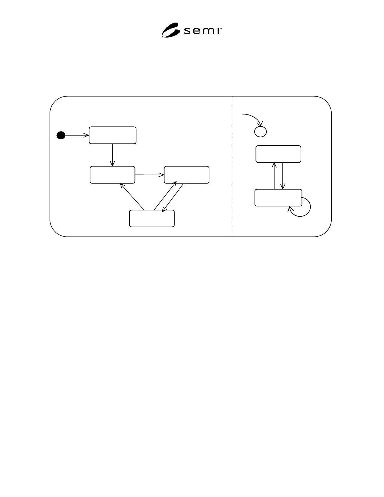
8.2.2 SC State Model
PAUSED
PAUSING
AUTO
ALARMS
NO ALARMS
SC INIT
6
3
4
8 7
AVAILABILITY
SYSTEM
5
2
1
9
C
Figure 3
Generic Stocker SEM SC State Model Diagram
8.2.3 SC State Definitions
8.2.3.1 SC INIT — SC initialization of stocker components is occurring. This is a non-operational state. No
commands from the host will be acknowledged, queued or processed. The system will not move out of this state if
there are carriers moving on any of the stocker units controlled by the SC. Such devices must be manually or
automatically recovered before transitioning to the next state.
8.2.3.2 PAUSING — A system PAUSE command has been received and is being processed. All carriers that are
currently moving will continue until their physical movement stops (their transfer command may still be active).
Carriers that are currently moving may continue to move but they must not begin another movement. TRANSFER
commands are accepted and queued. All status requests will be processed. The RESUME, INSTALL, REMOVE,
and LOCATE commands will also be processed.
8.2.3.3 PAUSED — No carriers are in the process of moving on any of the stocker units controlled by the SC.
Carriers may be at any port position including the OP, BP, and LP positions. TRANSFER commands are accepted
and queued. All status requests will be processed. The RESUME, INSTALL, REMOVE, and LOCATE commands
will also be processed.
8.2.3.4 AUTO — Stocker is in the normal operational state. Commands are actively processed.
8.2.3.5 NO ALARMS — There are no alarms present in the system.
8.2.3.6 ALARMS — There are one or more alarms present in the system.