semi合集-English.pdf - 第257页
SEMI E43-0301 © SEMI 1995 , 2001 5 9.2.3 Measurement Limitations — Me a s u r e m e n t s made to this guide are only v alid for surfaces that are flat to a radius of 1.5 times th e measurement distance from a point dire…

SEMI E43-0301 © SEMI 1995, 2001 4
workstation setup/conditions. However, any measure-
ment that is in excess of a (user) defined maximum or
that is a benchmark value, should be repeated more than
once, after performing a zero check of the measuring
equipment. This is to validate previous reading(s)
and/or establish a range/bounds in the case of varying-
moving fields on previous reading(s).
9 Test Methods & Measurem ents
9.1 Coulombmeter Measurements
9.1.1 Verifying the Coulombmeter — Verify the
performance of the coulombmeter as in Section 7
above. Check/reset the zero before each measurement
and/or per manufacturer's instructions. Assure that the
coulombmeter and operator are grounded.
9.1.2 Equipment Selection — Use a coulombmeter for
direct measurement of charge. A feedback-type
coulombmeter is recommended for charge
measurements for the most complete transfer of charge.
Shunt-type coulombmeters do not completely transfer
charge and are not as straightforward to use as
feedback-type coulombmeters. When using a Faraday
enclosure, the Faraday enclosure must be large enough
to hold the objects to be measured. The Faraday
enclosure is used to measure charge on insulating
materials as well as on conductors.
9.1.3 Measurements — Best results are achieved when
all surfaces surrounding the measurement area are
grounded (to minimize the effects of stray fields on the
measurement) and when a consistent, systematic
handling method is used during the measurement
process. The operator should be grounded using a
grounded wrist strap.
9.1.3.1 Isolated Conductors — To measure the charge
on an isolated conductor, touch the lead from the
coulombmeter to the isolated conductor.
9.1.3.2 Faraday Enclosure Measurements — Refer to
Figure 3. To measure the charge on an object, carefully
pick up the object with an insulated tool and place the
charged object into the Faraday enclosure. Special
handling considerations: Be careful not to add or
subtract any charge in the process of moving the
charged object into the Faraday enclosure. Don’t let the
charged object rub or slide against any other surface, as
this may add or subtract charge from the object.
9.1.4 Limitations — Do not attempt to measure
charges of magnitudes that are below the drift rate of
the coulombmeter.
9.2 Electrostatic Fieldmeter Measurements
9.2.1 Verifying the Fieldmeter — Verify the
performance of the fieldmeter as in Section 7 above.
Check/reset the zero periodically and/or per
manufacturer's instructions. Assure that the fieldmeter
and operator are grounded.
9.2.2 Measurements — Measurements made to this
guide should be taken/reported in units that conform to
the customer specifications. Most common fieldmeters
manufactured to date have operating instructions that
reflect the user doing calibration and taking
measurements in English units of volts/inch or volts at a
fixed distance in inch(es) and in these cases, raw data
are reported/listed directly. The international
community specifies that units shall be in SI (Standard
International) Metric units and the SI conversion factor
in Section 7.1.1.1 will apply. However, by definition,
electric field is expressed in volts per meter, and thus
would be expressed according to Table 2.
9.2.2.1 For instance, when using a meter calibrated
only at 100 volts, measurements under 4,000 volts/m
would be expressed to the nearest 400 volts/m.
Measurements over 4,000 volts/m would be expressed
as > 4,000 volts/m. For a meter calibrated to all three
voltages, measurements under 4,000 volts/m would be
expressed to the nearest 400 volts/m, measurements
between 4,000 and 40,000 volts/m would be expressed
to the nearest 4,000 volts/m, and measurements over
40,000 volts/m would be expressed to the nearest
40,000 volts/m.
Table 2 Measurement Units
Test Voltage For Readings of Express in Multiples of For Readings of Express as
100 V < 4,000 V/m 400 V/m > 4,000 V/m > 4,000 V/m
1,000 V < 40,000 V/m 4,000 V/m > 40,000 V/m > 40,000 V/m
5,000 V < 200,000 V/m 20,000 V/m > 200,000 V/m multiples of 200,000 V/m
Note: Measurements above 1000 volts/2.54 cm may be made based on verification of the meter at 1000 volts where less precision is acceptable
due to safety concerns with verification equipment/setup or availability of such equipment.

SEMI E43-0301 © SEMI 1995, 20015
9.2.3 Measurement Limitations — Measurements
made to this guide are only valid for surfaces that are
flat to a radius of 1.5 times the measurement distance
from a point directly below the sensor head. For
surfaces that are not flat, measurements should be made
by moving the sensor over the surface such that the
specified measurement distance is maintained as closely
as possible. These measurements may only be stated as
a range, with rounding as applicable to the meter's
measurement range according to Section 9.2.2. See
Figure 4, Example of a Survey of a Carrier of
Semiconductor Wafers. See Related Information 2 for
notes on test methods environment and measurements.
9.3 Electrostatic Voltmeter Measurements — Refer to
Figure 4.
9.3.1 Verifying the Voltmeter — Verify the
performance of the voltmeter as in Section 7 above.
Check/reset the zero periodically per manufacturer's
instructions. Assure that the voltmeter and operator are
grounded.
9.3.2 Selecting the Voltmeter — Select an electrostatic
voltmeter with a measurement range consistent with the
anticipated levels of charge on the objects to be
measured. The selection of too high a measurement
range will sacrifice voltage resolution, while selection
of too low a range will cause out-of-range operation
(saturation).
9.3.2.1 To measure moving objects, select an
electrostatic voltmeter with a response speed fast
enough to detect the objects when they are moving past
the electrostatic voltmeter probe at the highest
anticipated velocity.
9.3.2.2 Select a side- or end-viewing probe for the
electrostatic voltmeter as is best suited to view the
target object or surface when the probe is installed in an
apparatus.
9.3.3 Measurements — Position the probe in front of
the surface to be measured. Best results are obtained
when the probe is placed less than two (probe) aperture
diameters from the object or surface to be measured.
At these closer spacings, the effects of extraneous fields
are minimized.
9.3.3.1 To resolve a small surface area, the distance
between the probe and the surface-under-measurement
must be less than 1/5
th
of the diameter of the surface
area to be measured. At wider spacings the surface area
resolved by the probe will exceed the surface area of
interest, and measurement accuracy may be reduced
together with the possibility of introducing effects of
extraneous fields to the measurement.
9.3.4 Measurement Limitations — Voltage levels on
isolated conductors can be measured. Insulators do not
have a uniform surface charge distribution. Therefore,
it is considered that voltage levels measured on
insulators indicate an electrostatic field strength in a
particular area.
9.4 Electrometer Measurements — Measuring with an
Electrometer is very similar to measuring with any
other voltmeter or multimeter.
9.4.1 Connect the “common” terminal of the
electrometer through a test lead to the reference plane
or ground. Connect the “hot” or signal lead to the object
or test point of interest. Some electrometer
measurements will use a separate wire or shield
connected to the electrical ground or a guard ring.
Connect this as recommended by the manufacturer of
the equipment.
9.4.2 The major difference between the ordinary
voltmeter and the electrometer is the orders of
magnitude higher input impedance of the electrometer.
An electrometer will therefore pick up voltage signals
produced by stray electric fields, potentials associated
with noise currents, and artifacts caused by intentional
or unintentional ionization of the ambient air when
measuring high voltages. An electrometer can, for
example, be used to measure the triboelectric and the
piezoelectric properties of a piece of coaxial cable:
connect the cable under test to the electrometer, and
flex it or tap on it with a finger. The voltages induced
on the center conductor can be measured by the
electrometer.
10 Certification
10.1 Certification to survey areas to this guide is for
the person doing the certification (certifier) to assure
that the person being certified (certifyee) can calibrate
the meter and make acceptable measurement of known
static field(s) per Section 7 and applicable example(s)
per Section 9. The certifier shall be someone qualified
by education and/or training to calibrate and make
measurements with the equipment called out in this
guide or someone previously certified. The ESD
Association conducts such training programs and the
National Association of Radio and Television
Engineers (NARTE) administers an ESD Engineer and
ESD technician certification program.
10.2 Demonstrating Ability to Verify the Performance
of the Meter Against Known Source — The certifyee
shall charge the test plate, zero the meter, and perform
the measurement a minimum of two times per Section
7; record values per Section 11. Readings obtained shall
be within 5% of expected values.
SEMI E43-0301 © SEMI 1995, 2001 6
10.3 Demonstrating Ability to Measure Example Item(s) Acceptably — The certifier will have charged/uncharged
example(s) of items/objects for measurement of static field(s) by certifyee(s) a minimum of two times per Section 9;
record values per Section 11.
10.4 Certifying — Readings obtained per Section 10.2 shall be within 12% of expected values and methodology of
obtaining readings shall be acceptable per certifier observation(s). A permanent record of certification is realized by
certifyee when certifier signs record sheet(s) for file in personnel records and/or when certifier issues a certificate.
Refer to Section R1-3.
11 Documentation
11.1 Meter calibration check(s), benchmark or laboratory measurements, items/areas surveys, and/or any other
electrostatic field measurements should be recorded in permanent records. Recorded are initial reading,
second/validation reading, and any subsequent readings taken to acceptable range/bound levels observed. Record
sheet(s) should show meter used, area (name), location, date, and items listed opposite readings, name of person
who took readings, and space for comments.
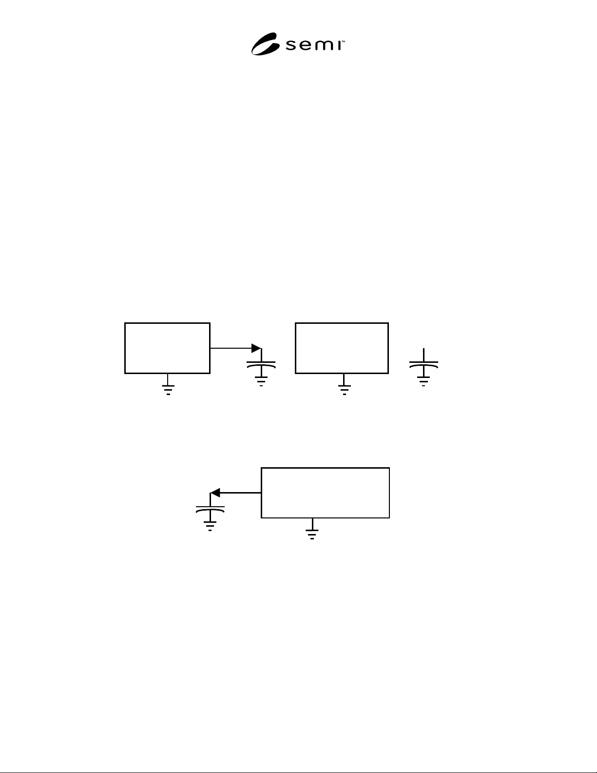
Charging
Source
STEP 1
Charge
Capacitor
Charging
Source
STEP 2
Disconnect
Charging
Source from
Capacitor
Coulombmeter
STEP 3
Connect
Coulombmeter
to Capacitor
Figure 1
Verifying Performance of the Coulombmeter