semi合集-English.pdf - 第2598页
SEMI E91-0600 © SEMI 1999 , 2000 3 5.1.2 Some equipment may need to i n c lude additional states. However, any additio nal states must not ch an ge the PSEM-defined state transitions. All expected transitions between PSE…
SEMI E91-0600 © SEMI 1999, 2000 2
4.8 job — a lot, processed with a s ingle process
program on PSEM equipment.
4.9 load — move material to the p robing or marking
location from the cassette.
4.10 lot — a group of one or more s ubstrates of the
same type (e.g., wafers, masks, CDs).
4.11 map — a list of coordinate positions of die on a
substrate. MAP is defined in accordance with SEMI
M21 in this document.
4.12 map data — the categorized d ata of die as a
result of measurement associated with coordinates.
Map data also have an information that identifies origin
die.
4.13 marking — the process of the prober that making
an ink mark on a die using the inker.
4.14 material — 1. The basic unit o f process,
physically a cassette or some cassettes. 2. A lot.
4.15 measurement — making a test , contacting the
probe card and the die. The tester sends to the prober a
categorized data as a result of test.
4.16 probe card — the electromech anical interface
necessary to enable temporary electrical contact
between the substrate to be tested and the tester
resource. May consist of multiple components.
4.17 re-inspection — a process whe re the same
substrate is tested again by using the inspected map
data.
4.18 slot — a physical location with in a cassette
capable of containing a substrate. (Also referred to as a
carrier location).
4.19 state — 1. A static set of cond itions. If the
conditions are met, the state is current (SEMI E30). 2.
A state reacts predictably to specific stimuli.
4.20 substrate — 1. The basic unit of material,
processed by PSEM equipment such as wafers.
4.21 testing equipment — an equipment class
generally consisting of integrated mechanisms and
controls for performing electrical tests of packaged
devices and or wafer die during the manufacturing
process.
4.22 unload — remove materials to the cassette slots
from the probing or marking location.
4.23 wafer end — the end of measuring process of a
wafer.
5 State Model
5.1 The purpose is to define the eq uipment-specific
processing state model and Prober Job state models
necessary to portray the expected operational states of
the equipment to enable host tracking and control in
place of a local operator.
5.1.1 The processing state models in this document are
required for implementing an PSEM-compliant prober,
in addition to the required state models in SEMI E30. A
state model consists of a state model diagram, state
definitions, and a state transitions’ table. A state model
represents the host’s view of the prober, but not
necessarily the actual prober operations. All PSEM
state model transitions shall be mapped sequentially
into the actual equipment events that satisfy the
requirements of those transitions. In certain
implementations, the prober may enter a state and has
already satisfied all of the conditions required by the
PSEM state model for transition to another state. In this
situation, the prober makes the required transition
without any additional actions.
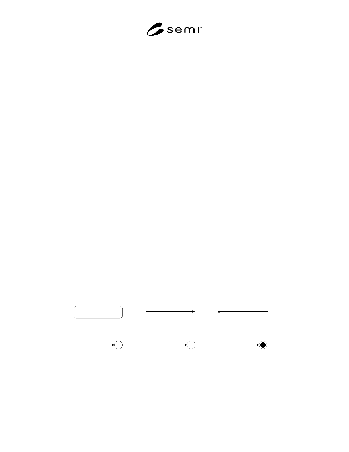
5.1.1.1 Various symbols used in a state diagram are
described in Figure 1.
a) State
b) Transition
c) Default Entry Point
H
d) History
C
e) Conditional Selector
f) Terminator
Figure 1
Various Symbols Used in a State Diagram
SEMI E91-0600 © SEMI 1999, 20003
5.1.2 Some equipment may need to include additional
states. However, any additional states must not change
the PSEM-defined state transitions. All expected
transitions between PSEM states must occur.
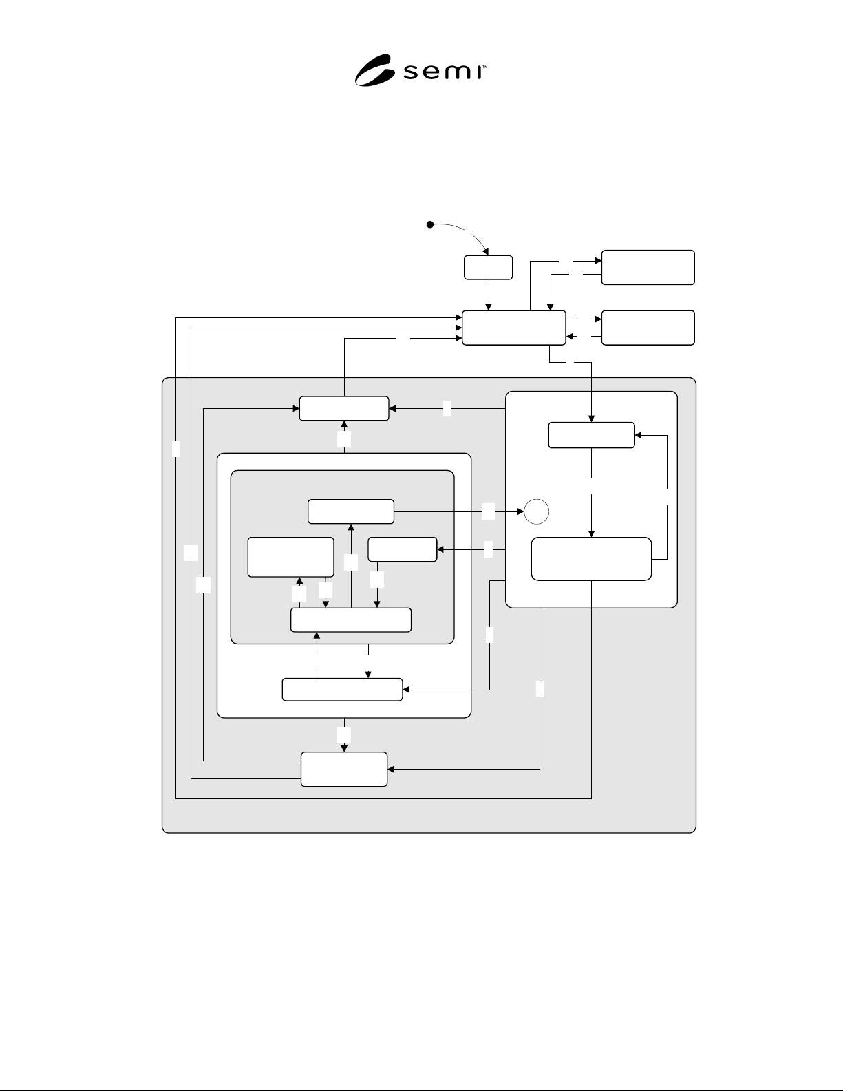
5.2 PSEM Processing State Model
5.2.1 Purpose
5.2.1.1 The purpose of the PSEM Processing State
Model is to make an accurate model for the behavior of
the PSEM prober from Processing State Model defined
in SEMI E30.
5.2.2 PSEM Processing State Model Diagram
INIT
IDLE with
Alarms
IDLE
EXECUTING
(PROBING)
MAINTENANCE
ABORTING
CHECKING
PAUSED
SETTING UP
PAUSING
PAUSED
ALARM PAUSED
STOPPING
2
3
4
7
8
9
C
10
11
12
6
21
13
18
17
16
19
15
14
20
23
24
25
26
PROCESS PAUSE
PAUSE
PROCESSING ACTIVE
PROCESS
SETTING UP
22
5
1
Figure 2
PSEM Processing State Model Diagram

SEMI E91-0600 © SEMI 1999, 2000 4
5.2.3 Description of Prober Processing States
5.2.3.1 ABORTING (PROCESSING ACTIVE Sub-
state) — The prober has received ABORT command.
All activities are suspended. The prober is taking an
appropriate action to ensure possible safe state for the
prober itself and materials. Wafer data or lot data may
be unavailable.
5.2.3.2 ALARM PAUSED (PAUSE Sub-state) — An
alarm has occurred in PROCESS or PROCESS PAUSE
state. The prober is waiting for the alarm to be cleared.
5.2.3.3 CHECKING (PROCESS PAUSE Sub-state) —
The prober verifies that a process program update
performed is valid. This is a procedure same with that
taken in SETTING UP state before the prober is ready
to transit to READY state. Upon completion of
verification, an event will be created if the verification
is successfully ended. A transition is made to the
process state, based on the process model condition
table.
5.2.3.4 EXECUTING (PROCESS Sub-state) — The
prober is processing material automatically and can
continue to do so without external intervention. This
state may include interaction with the host or operator.
5.2.3.5 IDLE — The prober is waiting for an
instruction. IDLE is free of ALARMS and error
conditions.
5.2.3.6 IDLE with ALARMS — An alarm has occurred
in the IDLE state and the prober is waiting for all
alarms to be cleared.
5.2.3.7 INIT — Prober is in the course of initialization.
5.2.3.8 MAINTENANCE
5.2.3.8.1 The operator’s instruction has disabled
production by the prober.
5.2.3.8.2 Maintenance and inspection of the prober are
executed in this state.
5.2.3.9 PAUSE (PROCESSING ACTIVE Sub-state) —
PROCESS state is interrupted when the processing can
be paused. An action to ensure safety of the prober is
taken. The prober waits for a command (RESUME,
STOP or ABORT) or the alarm to be cleared.
5.2.3.10 PAUSED (PROCESS PAUSE Sub-state) —
In this state an operator can correct an error as far as the
current process program selection is not affected.
PROCESS state is suspended and the prober waits for a
command (RESUME, STOP or ABORT). In this state,
the operator is allowed to correct an error conditions
that does not affect the current process program
selected. One of such corrective actions that can be
taken by the operator is manual alignment of the wafer
in process.
5.2.3.11 PAUSED SETTING UP (PROCESS PAUSE
Sub-state) — When PROCESS state is suspended, the
prober is made to perform simple set-up operations.
Probe card replacing work and inker replacing work are
included in those operations.
5.2.3.12 PAUSING (PROCESS PAUSE Sub-state) —
PROCESS state is interrupted when the processing can
be paused. The prober cannot transit to PAUSED state
until safe state is ensured.
5.2.3.13 PROCESS (PROCESSING ACTIVE Sub-
state) — This state is the parent of those sub-states that
refer to the preparation and execution of a process
program.
5.2.3.14 PROCESS PAUSE (PAUSE Sub-state) —
The prober is free of alarm conditions in the PAUSE
state.
5.2.3.15 PROCESSING ACTIVE — The state in which
the prober is processing materials.
5.2.3.16 SETTING UP (PROCESS Sub-state) — The
prober is trying to satisfy requirements to be able to
start processing. This is the state under which the
prober has already received a process program and
materials to be processed, then has received START
command from the host or the operator and is making
preparation for the processing according to the process
program.
5.2.3.17 STOPPING (PROCESSING ACTIVE Sub-
state) — The prober has received STOP command and
sets up for the stop. All necessary cleanup is completed
within this state with regard to material, data, control
system, etc. Data is preserved. Any error condition is
cleared before exiting from this state.