semi合集-English.pdf - 第2607页
SEMI E91-0600 © SEMI 1999 , 2000 12 ......... PARA M_RECORD00:str ucture cla ss name / clas s name/proc ess pr ogram rec ord name ......... PARAM_RECO RDnn:structure cla ss name/class na me/process progra m record name 8…
SEMI E91-0600 © SEMI 1999, 200011
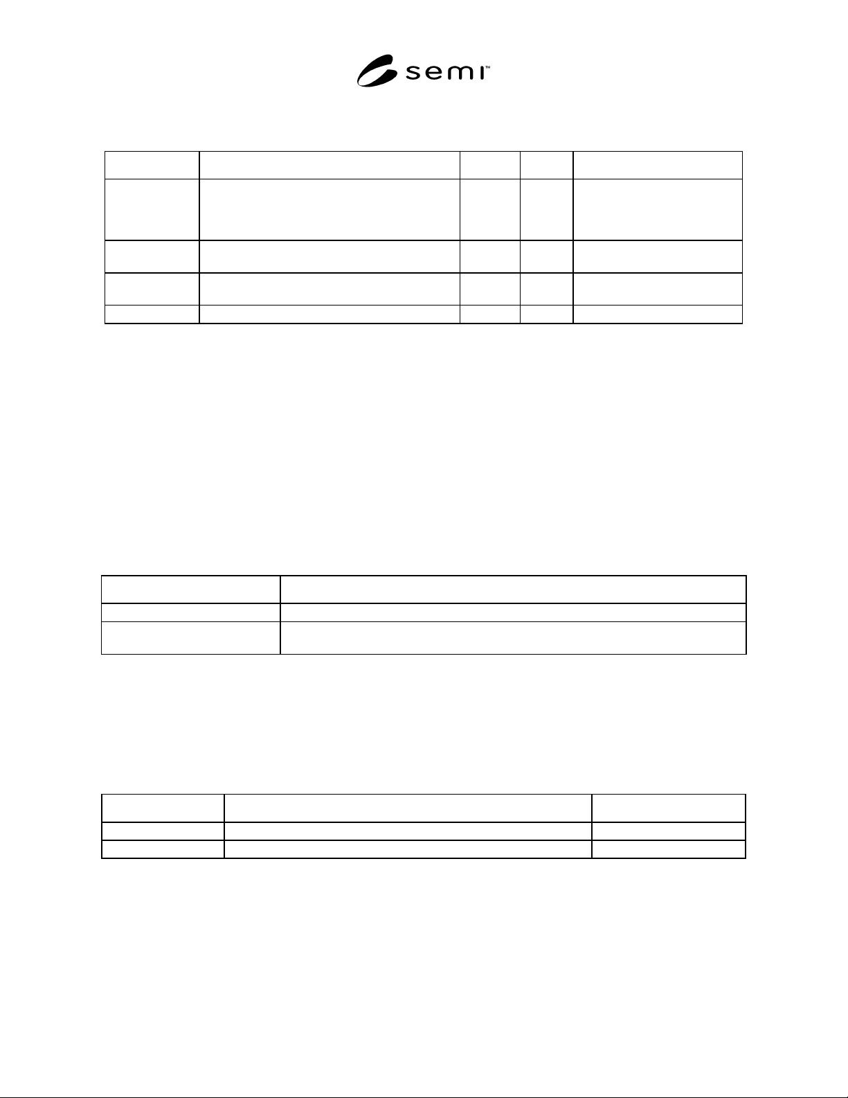
7.4 Data Item Variable Table
Table 7 Data Item Variable Table
Variable Name Description Class Format Comments
StopUnit Constant which specifies separation of stop
operation in probing.
ECV U1 0=Unit of Die
1=Unit of Wafer
2=Unit of Cassette
3=Unit of Lot
EventJobID Prober Job ID which occurs Prober Job state
transition.
DVVAL A[30] Valid when Prober Job state
transition occurs.
EventJobState Current state of Prober Job whose state changed. DVVAL U2 Valid in event of Prober Job
state transition.
ResultData Processing result in unit of one wafer. DVVAL L[n] Valid only in wafer end event.
8 Process Program Manage ment
8.1 PSEM explains how to specify a process program for the prober and the process program control between the
host and prober.
8.2 Process Program Requirements
8.2.1 The PSEM requires that the G EM capability of process program management be fully supported for this class
of prober.
8.3 Process Program
8.3.1 The process program of the prober consists of the main process program and two or more sub process
programs that are referred to by the main process program.
Table 8 Kinds and Descriptions of Process Programs
Kind Description
Product type master record Master process program for processing.
Sub-parameter record Sub-process program for processing.
Various kinds of parameter records that consist main process program for processing.
8.3.2 These process programs are controlled by the prober with grouped into different categories according to
application purposes and structures. The prober defines PPID with “structure class name/class name/process
program record name.” The number of PPID digits is defined by an equipment supplier. If the number of the digits
is less than a default value, left-justify and fill in space after PPID. Do not use space at some midpoint in PPID. At
present, the prober practically uses the structure class name and class name as shown in the table given below.
Table 9 How to Operate Class Name and Structural Class Name
Classification Operation Remarks
Structural class name Class name indicating major classification of process program record. Defined by supplier.
Class name Class name indicating attribute of process program record. Defined by supplier.
8.4 Master Process Program Reco rd
8.4.1 The master process program re cord is a plain text (ASCII) record like below:
DEVICE:xxxxxxxx
WAFER_SIZE:xx
DIE_SIZE:xxxxxx,xxxxxx
SEMI E91-0600 © SEMI 1999, 2000 12
.........
PARAM_RECORD00:structure class name/class name/process program record name
.........
PARAM_RECORDnn:structure class name/class name/process program record name
8.4.1.1 Each line has a structure:
TAG + ":" + parameter(s) + line terminator
8.4.1.2 The line terminator is some of CR+LF (0x0d0a), CR (0x0d), LF (0x0a).
8.4.1.3 Specific parameters of equipment supplier may be put between "HOT_CHUCK_TOLE" and
"PARAM_FILE00".
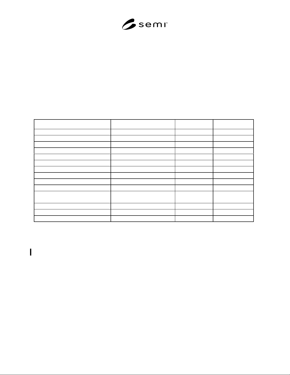
Table 10 Tag Parameters in Master Process Program
Tag Description Format Unit
PRODID Product name (i.e., Device type) A[1,24] -
WAFER_SIZE Wafer size A[1,3] mm
DIE_SIZE_X Die size X A[1,6] micron
DIE_SIZE_Y Die size Y A[1,6] micron
MULTI_DIE Multi probing number A[1,3] -
REFERENCE_DIE_COORD_X Reference die coordinator X A[1,4] -
REFERENCE_DIE_COORD_Y Reference die coordinator Y A[1,4] -
OVER_DRIVE Over drive value A[1,4] micron
FLAT_ANGLE Flat orientation A[1,3] degree
FLAT_TYPE FLAT or NOTCH A[1,5] -
HOT_CHUCK Flag of hot chuck usage A[2,3]
“ON” or “OFF”
-
HOT_CHUCK_TEMP Hot chuck temperature A[1,4] Celsius
HOT_CHUCK_TOLE Hot chuck tolerance A[1,3] Celsius
PARAM_RECORDnn Sub-parameter record nn A[ ] -
9 Map Data
9.1 This section defines handling o f map data in the PSEM equipment. The contents of map data are not defined
here. The specification in this section is provisional. This will be revised in the near future.
9.2 Use of Map Data
9.2.1 Map data is divided into two groups: result data which is reported to the host when processing of each wafer
is completed and instruction data which is instructed by the host in a unit of wafer at the time of re-inspection or
marking.
9.3 Structure of Map Data
9.3.1 The map data has a list structu re and the result data is defined by class <DVVAL> and the instruction data is
defined by <CEPVAL>.
9.3.1.1 Example:
<ResultData>
L,n
1. <Data
1
>
SEMI E91-0600 © SEMI 1999, 200013
:
n. <Data
n
>
9.4 Uploading (Reporting) Result Data
9.4.1 Result Data is reported by S6,F11 upon completion of the inspection in each wafer.
9.4.1.1 Example:
L,3
1. <DATAID>
2. <CEID>:Wafer End
3. L,a
1. L,2
1. <RPTID1>
2. L,7
1. <LOTID>
2. <PROCID>
3. <IDTYP>
4. <MID>
5. <ROWCOLCT>
6. <REFDIEPOS>
7. <ResultData>
:
a. L,2
1. <RPTIDa>
2. L,b
1. <LOC>
2. <PRODID>
3. <WAFSIZE>
4. <FLATTYPE>
5. <FLATANGL>
6. <REFDIECOORD>
7. <BINLIST>
:
b. <Vb>
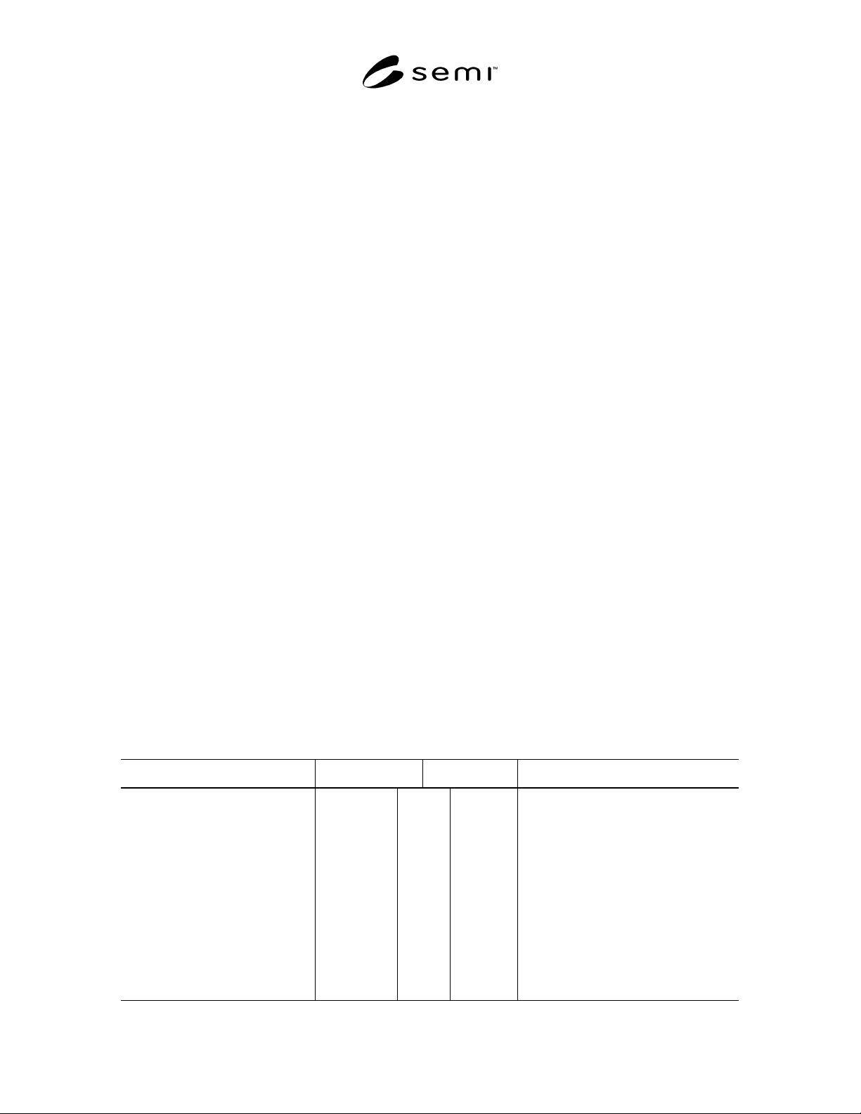
9.5 Downloading Instruction Data
9.5.1 If the past inspection result is required in processing a wafer, the equipment obtains instructed data from the
host in the following procedure.
Comment Host Equipment Comment
Transfer a wafer.
The equipment is ready to receive
previous result data for a wafer
concerned.
S6,F11 “Waiting Previous Data (wait for
reception of previous result data)” event
report.
Check event. S6,F12
Instruction data download
(PRE-DATA_DOWNLOAD)
S2,F49
S2,F50 Reception response.
The processing is performed based on
instruction data.