semi合集-English.pdf - 第2670页
SEMI E96-1101 © SEMI 1999 , 2001 10 Variants : None IDL module ControlStateModule { // Type Definitions enum ControlState {OFFLINE, LOCAL, REMOTE); interface ControlState { // Queries ControlState getControlState() raise…
SEMI E96-1101 © SEMI 1999, 20019
6.3.18.3 The description also includes all the side
effects and exceptions that can occur as a result of the
interactions related to the aspect.
6.3.18.4 If the aspect has any relation or effects related
to other aspects, they are also described here.
6.3.19 Variants If the aspect has variants, each
variant is named and described.
6.3.19.1 IDL Usually the IDL will include a special
module for the aspect. The module includes data type
definitions specific to the aspect and usually a single
interface that provides the various queries and
commands of the aspect. An aspect that has variants has
an interface per variant. The interfaces for the variants
can be inherited from a common (abstract) aspect
interface.
6.3.19.1.1 An aspect that deals with service requests
should also include an IDL definition for the server that
provides the services. Which is to be done in a separate
module.
6.3.19.2 Aspect Definition Example Here the
Control State Aspect has been chosen as an example for
aspect definition.
6.3.19.2.1 Aspect Name Control State
6.3.19.2.2 Aspect Description The definition of the
Control State Aspect is based on Generic Equipment
Model (GEM) SEMI standard E30.
NOTE 2: The state diagram presented here is simpler than the
one in SEMI E30, since the internal sub-states are irrelevant
to the productive entity interface, and the concept of HOST
OFFLNE is obsolete in a distributed factory environment
6.3.19.2.2.1 The control state model defines the level
of cooperation between the productive entity and the
factory. It also specifies how the operator interacts in
the different levels of factory control.
6.3.19.2.2.2 The control state model provides the
factory with three levels of control over the productive
entity:
6.3.19.2.3 OFFLINE In the OFFLINE state,
operation of the productive entity is done by the
operator. In the OFFLINE state the productive entity
accepts a query to find out the current control state and
the command to change its control state, but rejects all
other queries or commands (raising the rejected
exception). While in the OFFLINE state the productive
entity produces no events and no service requests.
6.3.19.2.4 LOCAL In the LOCAL state the
productive entity is operated by the operator.
6.3.19.2.4.1 In the LOCAL state the productive entity
answers all queries from the factory and allows the
factory to execute a limited set of commands. The
commands that are prohibited are those that cause
movement or directly affect the process. The productive
entity sends events and asks for services from the
factory.
6.3.19.2.5 REMOTE In the REMOTE state the
productive entity is controlled by the factory. The
factory has full access to all the necessary commands to
operate the productive entity through the full process
cycle in an automated manner. The degree of
automation can vary from productive entity to
productive entity and from factory to factory. Generally
operators are required to intervene in setup operations,
operator assist situations, etc. Therefore when in
REMOTE state, even though theoretically fully under
control of the factory, the productive entity should not
restrict the operator from executing essential operations
such as selecting a recipe, pausing or resuming the
process, operator assists, material movement to/from
the productive entity, initiating recipe download and
other productive entity specific commands on a
command by command basis as needed. At the very
least the operator should be able to change the control
state, actuate an emergency stop and interrupt
processing (stop, abort or pause).
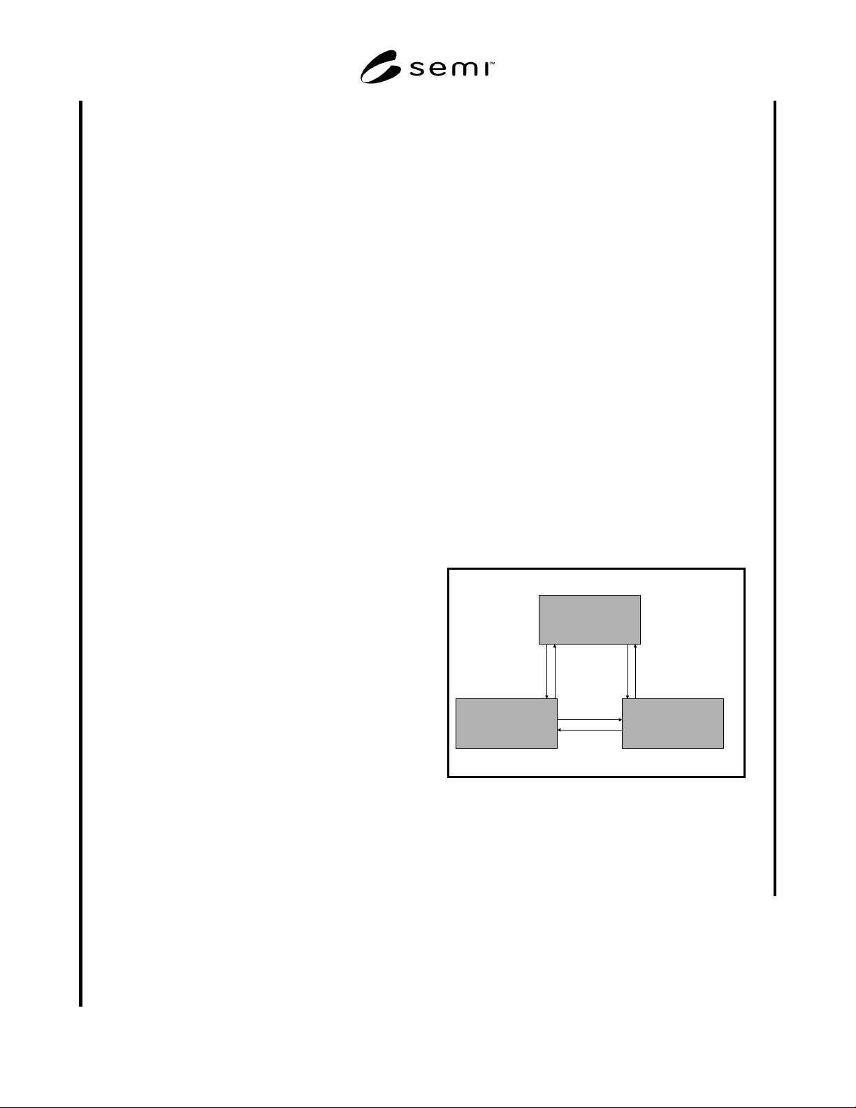
6.3.19.2.6 The following diagram depicts the
productive entity Control State model.
OFFLINE
LOCAL REMOTE
12 3 4
5
6
Figure 1
6.3.19.2.7 As can be seen from the diagram, transition
from any state is allowed to the two others. The aspect
provides the factory methods for querying the current
state, for initiating a transition to any of the states, and
for events when state transitions occur.

SEMI E96-1101 © SEMI 1999, 2001 10
Variants : None
IDL
module ControlStateModule {
// Type Definitions
enum ControlState {OFFLINE, LOCAL,
REMOTE);
interface ControlState {
// Queries
ControlState getControlState()
raises (EqBasicTypesModule::
CommunicationFailure);
// Commands
void changeControlStateToOffline()
raises (EqBasicTypesModule::
CommunicationFailure);
void changeControlStateToLocal()
raises (EqBasicTypesModule::
CommunicationFailure);
void changeControlStateToRemote()
raises (EqBasicTypesModule::
CommunicationFailure);
};
};
6.3.19.2.8 The control state aspect can post the
following events:
ControlStateChangedToLocal
ControlStateChangedToRemote
controlStateChangedToOffline
6.3.20 Interface Composition Mapping
6.3.20.1 The DCOM interfaces do not support multi-
ple inheritance. When multiple inheritance is used to
extend functionality, the mapping is not very difficult.
When multiple inheritance is used to “mix in” orthogo-
nal behavior the mapping is more difficult. The CIM
Framework interfaces that only use single inheritance
provide the most reliable mapping. Interfaces that use
multiple inheritance should follow the detailed mapping
rules and ordering provided in the CORBA
Interworking Architecture.
6.3.20.2 OLE Automation also has problems directly
supporting the multiple inheritance of CORBA. The
CORBA Interworking Architecture
4
provides detailed
mapping rules for making the conversion where
multiple inheritance is used.
6.3.21 Identity Mapping
6.3.21.1 CORBA and DCOM/OLE Automation have
different notions of what object identity means.
CORBA defines an object as a combination of the state
and a set of operations that explicitly define the
instance. An object reference is defined as a name that
reliably and consistently denotes an instantiated object.
A CORBA object exists until it is destroyed; its
lifecycle is controlled by the server.
6.3.21.2 DCOM does not provide the same mechanism
for identifying a particular object. DCOM objects are
usually created when used and their state does not
persist as an object instance. DCOM objects exist while
they are referenced; their lifecycle is controlled by the
client. This is true of OLE Automation objects as well.
6.3.21.3 The CORBA Interworking Architecture
provides mapping solutions for managing the object
lifecycle. The lifecycle issues should be minimized with
the CIM Framework use of component managers to
control object lifecycles. The implementation of
DCOM lifecycle mapping should be encapsulated in the
component manager.
6.3.22 Naming
6.3.22.1 As a mechanism to support initialization
between collaborating components, the name of each
component manager should be registered in a publicly
available namespace along with the object reference for
the component manager. The same name may be reused
unambiguously as long as all occurrences belong to
distinct namespaces. Other objects should be able to
obtain a handle (object reference) to each component
manager by utilizing the namespace through the
operations of a naming service. A trader service may
also be used to perform lookup of component managers
and other objects based on well documented search
criteria. Additional objects may also be registered in the
namespace or trader as appropriate. The component
manager serves as the namespace for the objects it
manages, providing object references for named
objects. Implementations should provide documentation
on how to obtain available object references in either
the namespace or the trader.
6.3.23 Memory Management
6.3.23.1 ORB implementations’ memory allocation
and deallocation services should handle all three types
of OMG IDL parameter passing:
• in –– Memory is caller-allocated and read-only.
The caller is responsible for memory deallocation.
• out –– Memory deallocation depends on the
specific usage of the argument.
• inout –– Memory allocation and deallocation
depend on the specific usage of the argument.
6.3.23.2 The CIM Framework uses only the in para-
meter passing mechanism. Within operations that have
had objects passed by reference, any modification of
the object occurs by using the in parameter as a refer-
ence. Supplier provided extensions to the CIM Frame-
work that use either the out or inout parameter passing
mechanism should document the caller and callee
responsibilities with respect to memory allocation and
deallocation.

SEMI E96-1101 © SEMI 1999, 200111
6.3.24 Use of OMG IDL Module Packaging Con-
structs
6.3.24.1 All IDL statements included as part of the
specification of SEMI E81 should be contained within
one or more CIM Framework defined modules.
6.3.24.2 CIMFW Module Conventions
6.3.24.2.1 Each CIM Framework sub-document that
specifies IDL declarations should provide a full listing
of the IDL statements in a compilable IDL file. This file
may be presented as an appendix to the specification
prior to final adoption and preparation for distribution
with the standard. The IDL file should include module
statements to enclose all IDL declarations for that
specification.
6.3.24.2.2 IDL files (or appendices) should begin with
a comment identifying the correct name of the file that
contains the enclosed IDL specification. The following
hypothetical example illustrates the form of this
comment.
//File: CIMFactoryLabor.idl
//Part of the CIM Framework for the
Factory Labor Component
6.3.24.2.3 Every IDL appendix should contain the
following statement identifying the top-level module
that contains all CIM Framework declarations.
module CIMFW{
...
};
6.3.24.3 Lower Level Modules within the CIM
Framework Module
6.3.24.3.1 The CIM Framework module should enclose
second level modules that further package each
partition of the CIM Framework specification as
defined in SEMI E81. All IDL declarations should thus
be scoped, first, to the CIM Framework, and second, to
the specific component of the framework. The fol-
lowing example illustrates the positioning of elements
of the Factory Labor component within a component
module.
module CIMFW{
module FactoryLabor{
typedef ..., etc.
};
};
6.3.24.3.2 Subsequent decomposition of CIM Frame-
work specifications into a third level of module contain-
ment may be necessary in some places, but should be
avoided where possible to keep fully qualified names
from getting to an unworkable length.
6.3.24.4 Conventions for CIM Framework Dependen-
cies
6.3.24.4.1 Each CIM Framework IDL file should
include explicit statements identifying any other files in
the CIM Framework specification set that contain mod-
ules that are referenced. These statements should be in
the form of #include statements. In order to avoid
circular references among related modules, a specifi-
cation may need to partition a module into more than
one file and include parts of the module at different
points in the referencing file. This structure of IDL files
is dependent on the specific implementation and which
parts of the CIM Framework it implements and may be
adjusted as needed to achieve successful compiles. The
IDL files distributed with the standard should suggest a
file structure to achieve a successful compile, but
should not indicate that the file structure is specified as
a part of the standard. The following example illustrates
an include statement.
#include <CIMGlobal.idl>
module CIMFW{ ...
6.3.24.4.2 All references to elements of separate mod-
ules will then need to be fully qualified with the module
scoping. For example, to reference a type defined in
the CIMGlobal module, the reference should take a
form similar to the following hypothetical example:
#include <CIMGlobal.idl>
module CIMFW{
module FactoryLabor{ ...
Global::MachineSequence
assignedMachines ()
raises
(Global::FrameworkErrorSignal);
};
};
6.3.24.4.3 Fully qualified names may also be
automatically generated if the target programming
language compiler supports the “namespace” concepts.
For example, the C++ standard uses namespace and
Java uses package to support namespaces.
6.3.24.5 Guard Statements
6.3.24.5.1 To avoid the possibility of the same CIM
Framework file being included more than once and thus
causing multiple definition errors, each module should
be preceded by the following type of guard statement.