semi合集-English.pdf - 第2895页
SEMI E109-0305 © SEMI 2001, 2005 5 Additional at tributes m ay be specified by t h e user or the equipm ent supplier by using an attri bute name st arting with “UD” (User Defined). Care should be taken to ensure the na…

SEMI E109-0305 © SEMI 2001, 2005 4
6 Requirements
6.1 Reticle and Pod Management compliant equipment is required to provide certain capabilities defined by other
standards: accessibility to status information, event reporting, alarm management, and equipment control. These
requirements shall be satisfied through compliance to the following sets of standards:
6.2 Generic Equipment Model Standard (GEM) SEMI E30
Event Notification
Status Data Collection
Equipment Constants
Alarm Management
Equipment Control
Remote Control
Error Messages
Dynamic Event Report Configuration
6.3 Object-Based Standards
Object Services Standard (SEMI E39)
Event Reporting (SEMI E53)
Exception Management (SEMI E41)
7 Conventions
7.1 Objects
7.1.1 Whenever the equipment is required to know about specific kinds of entities, and required to manage
information concerning these entities, it is useful to treat these entities as objects that comply with the basic
requirements of SEMI E39 (OSS). This is especially true whenever there are a large number of objects of a given
type or when the entities are transient rather than permanent. In both cases, it is difficult to describe a general way
for the host and equipment to specify which particular entity is referenced and to get information related only to a
specific one out of many.
7.1.2 By defining these entities as objects that comply with SEMI E39, it is only necessary for the host to specify
the type of object and its specific identifier in order to inquire about one or more properties of the specific entity of
interest.
7.1.3 Object Properties
7.1.3.1 A property (attribute) is information about an individual object that is presented as a name/value pair. The
name is a formally reserved text string that represents the property, and the value is the current setting for that
property.
7.1.3.2 Properties shall be accessible to the host via the service GetAttr and SetAttr for the Reticle Pod object,
Reticle object, and Reticle location object:
get the list of IDs for the current reticle pods at the equipment, and
get the specified properties for one or more individual reticle pods.
7.1.4
Rules for Object Properties
Attributes with RO access can not be changed using SetAttr service as defined in OSS.
Attributes with RW access can be changed using SetAttr service as defined in OSS.
SEMI E109-0305 © SEMI 2001, 2005 5
Additional attributes may be specified by the user or the equipment supplier by using an attribute name starting
with “UD” (User Defined). Care should be taken to ensure the name of the attribute is unique.
7.1.5 Object Attribute Table
7.1.5.1 The object attribute table is used to list all the attributes related to the defined object as shown below the
access is defined as Read only (RO) or Read/Write (RW). The REQD column is used to specify whether the
attribute is required for implementation. Finally, the Form column is used to specify the format of that particular
attribute.
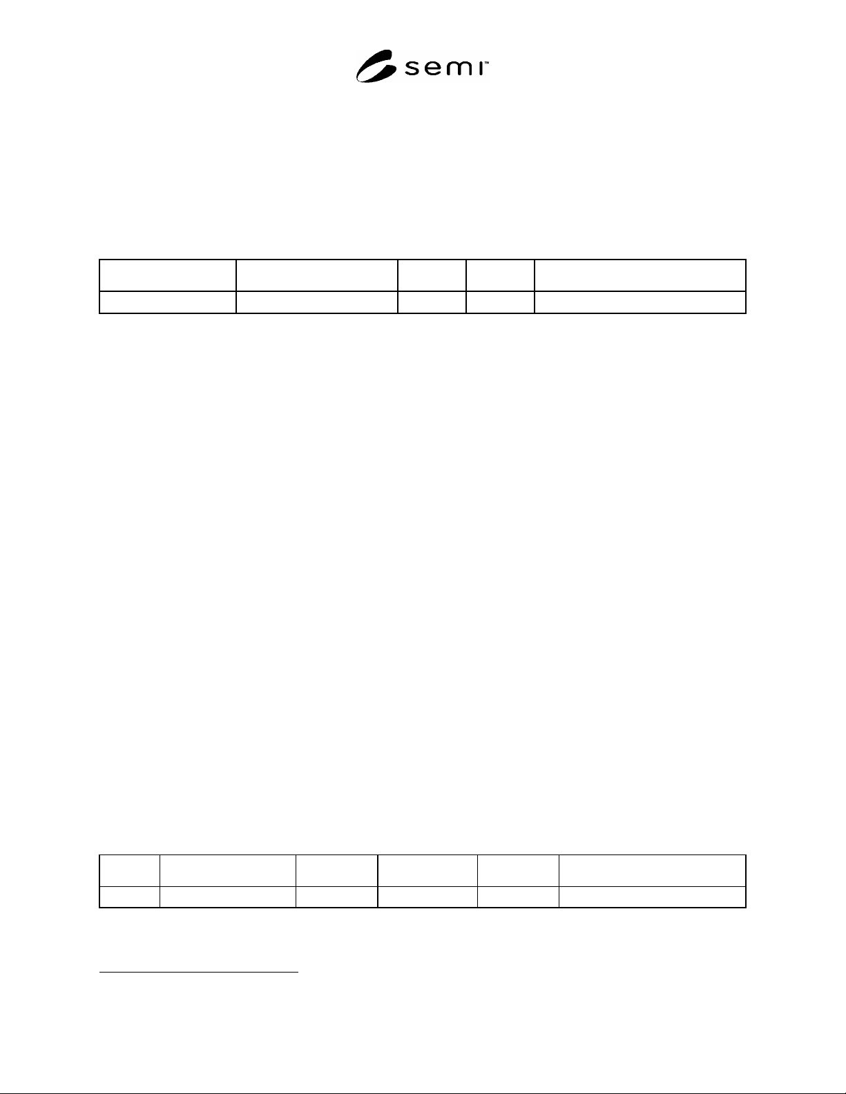
Table 1 Object Attribute Table
Attribute Name Definition Access Reqd Form
ObjType Object type RO Y Text = “Carrier”
7.2 State Model Methodology
7.2.1 A state model has three elements: definitions of each state and sub-state, a diagram of the states and the
transitions between states, and a state transition table. The diagram of the state model uses the Harel State Chart
notation. An overview of this notation is presented in an Appendix of SEMI E30. The definition of this notation is
presented in Science of Computer Programming 8, “Statecharts: A Visual Formalism for Complex Systems”, by D.
Harel, 1987.
1
7.2.2 State Model Requirements
7.2.2.1 The state models included in this standard are a requirement for RPMS compliance. A state model consists
of a state model diagram, state definitions, and a state transition table. All state transitions in this standard, unless
otherwise specified, shall correspond to collection events.
7.2.2.2 A state model represents the host’s view of the equipment, and does not necessarily describe the internal
equipment operation. All Reticle and Pod Management state model transitions shall be mapped sequentially into the
appropriate internal equipment collection events that satisfy the requirements of those transitions. In certain
implementations, the equipment may enter a state and have already satisfied all of the conditions required by the
RPMS state model for transition to another state. In this case, the equipment makes the required transition without
any additional actions in this situation.
7.2.2.3 Some equipment may need to include additional sub-states other than those in this standard. Additional sub-
states may be added, but shall not change the Reticle and Pod Management defined state transitions. All expected
transitions between Reticle and Pod Management states shall occur.
7.2.2.4 Transition tables are provided in conjunction with the state diagrams to explicitly describe the nature of each
state transition. A transition table contains columns for Transition number, Previous State, Trigger, New State,
Actions, and Comments. The “trigger” (column 3) for the transition occurs while in the “previous” state. The
“actions” (column 5) includes a combination of:
Actions taken upon exit of the previous state,
Actions taken upon entry of the new state, and
Actions taken which are most closely associated with the transition.
Table 2 State Transition Table
Num Previous State Trigger New State Actions Comments
1 Elsevier Science, P. O. Box 945, New York, NY 10159-0945, http://www.elsevier.nl/homepage/browse.html
SEMI E109-0305 © SEMI 2001, 2005 6
7.3 Services
7.3.1 Services are functions or methods that may be provided by either the equipment or the host. A service
message may be either a request message, which always requires a response, or a notification message that does not
require a response.
7.3.2 Service Message Description
7.3.2.1 A service message description table defines the parameters used in a service, as shown in the following
table:
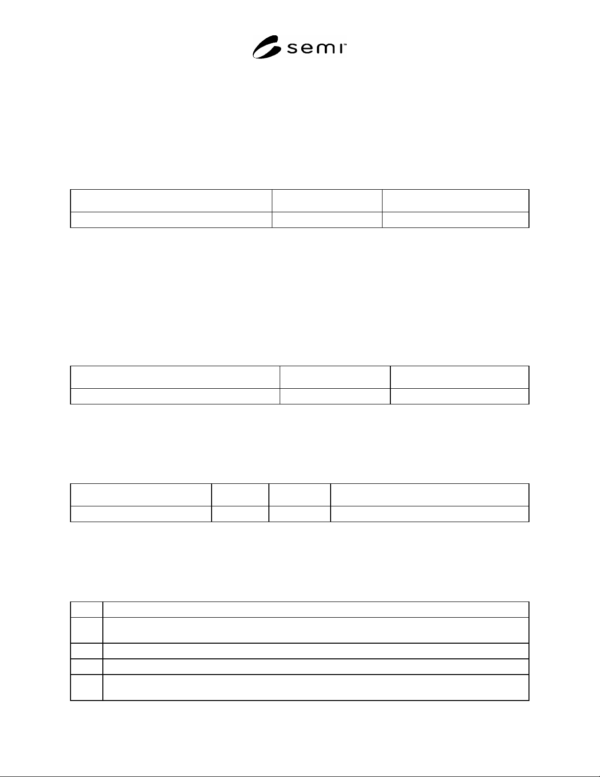
Table 3 Service Message Description Table
Service Name Type Description
#1
Type can be either “N” = Notification or “R” = Request & Response.
7.3.2.2 Notification type messages are initiated by the service provider (e.g., the equipment) and the provider does
not expect to get a response from the service user. Request messages are initiated by a service user (e.g., the host).
Request messages ask for data or an activity from the provider. Request messages expect a specific response
message (no presumption on the message content).
7.3.3 Service Message Parameter Definition
7.3.3.1 A service parameter dictionary table defines the description, range, and type for parameters used by
services, as shown in the following table:
Table 4 Service Message Parameter Definition Table
Parameter Name Form Description
#1
A row is provided in the table for each parameter used on a service.
7.3.4 Service Message Definition
7.3.4.1 A service message description table defines the parameters used in a service message. It also describes each
message and its cause/effect to the equipment. The columns labeled Req/Ind and Resp/Conf link the parameters to
the direction of the message.
Service Parameter Req/Ind Resp/Conf Description
7.3.4.2 The columns labeled Req/Ind and Rsp/Conf link the parameters to the direction of the message. The
message sent by the initiator is called the “Request”. The receiver terms this message the “Indication”. The receiver
may then send a “Response”, which the original sender terms the “Confirmation”.
7.3.4.3 The following codes appear in the Req/Ind and Rsp/Conf columns and are used in the definition of the
parameters (e.g., how each parameter is used in each direction):
“M” Mandatory Parameter – must be given a valid value.
“C” Conditional Parameter – may be defined in some circumstances and undefined in others. Whether a value is given may
be completely optional or may depend on the values of other parameters.
“U” User-Defined Parameter.
“-” The parameter is not used.
“=” (for response only) Indicates that the value of this parameter in the response must match that in the primary (if
defined).