semi合集-English.pdf - 第3021页
SEMI E122-0703 © SEMI 2003 2 5.1.3 datal og — collect ion of results of individu al test measurements gathered during the execution of the test program. 5.1.4 diagnostic fixture — any electromechanical fixture requir ed …

SEMI E122-0703 © SEMI 2003 1
SEMI E122-0703
STANDARD FOR TESTER EQUIPMENT SPECIFIC EQUIPMENT
MODEL (TSEM)
This standard was technically approved by the Global Information and Control Committee and is the direct
responsibility of the North American Information and Control Committee. Current edition approved by the
North American Regional Standards Committee on November 22, 2002. Initially available at www.semi.org
January 2003; to be published March 2003.
NOTICE: The designation of SEMI E122 was updated
during the 0703 publishing cycle to reflect the addition
of SEMI E122.1.
NOTICE: This standard replaces SEMI E30.3, which
has been removed from publication as of the March
2003 (0303) publication cycle.
1 Purpose
1.1 This document establishes a Specific Equipment
Model for testing equipment (TSEM). The TSEM
consists of equipment characteristics and behaviors that
apply to this class of equipment. These characteristics
and behaviors are required to be implemented. The
intent of this document is to facilitate the integration of
testing equipment into an automated semiconductor
factory. This document accomplishes this by defining
an operational model for testing equipment as viewed
by a factory automation controller. This definition
provides a standard host interface and equipment
operational behavior.
2 Scope
2.1 The document defines the view of the equipment
through the host communications link but does not
define the internal operation of the equipment. It
includes a specific processing state model as the basis
for the behavior of all equipment of this class.
2.2 This document expands testing equipment
requirements and capabilities in the areas of the
processing state model, collection events, alarm
documentation, remote commands, variable items, and
process program management.
NOTICE: This standard does not purport to address
safety issues, if any, associated with its use. It is the
responsibility of the users of this standard to establish
appropriate safety and health practices and determine
the applicability of regulatory or other limitations prior
to use.
3 Limitations
3.1 Communications
3.1.1 It is required that any TSEM-compliant
equipment follow the Communications State Model in
SEMI E30. In addition TSEM-compliant equipment
shall support the High-Speed Messaging Service (SEMI
E37) Communication Standard sending messages over
TCP/IP to maximize the amount of data available for
monitoring from this class of equipment. This
specification deals only with the behavior of the tester
in communicating with the host application
3.2 Virtual Tester
3.2.1 Section 7 of this document describes the concept
of the Virtual Tester. The requirements described in
this document must be fully implemented on each
virtual tester, independent of any other virtual tester.
For the purposes of this document, it can be assumed
that the term “tester” refers to the virtual tester as
defined in Section 7. Any references to the physical
tester will be explicitly noted.
4 Referenced Standards
4.1 SEMI Standards
SEMI E30 — Generic Model for Communications and
Control of Manufacturing Equipment (GEM)
SEMI E37 — High-Speed SECS Message Services
(HSMS) Generic Services
SEMI E37.1 — High-Speed SECS Message Services
Single Selected-Session Mode (HSMS-SS)
NOTICE: Unless otherwise indicated, all documents
cited shall be the latest published versions.
5 Terminology
5.1 Definitions
5.1.1 calibration fixture — any electromechanical
fixture required to perform system calibration. The
calibration fixture may consist of multiple components
with different part and serial numbers.
5.1.2 class — classes represent the most coarse view of
the test results. At a minimum, there should be two
classes defined for each process program: one class
representing good units and another class representing
failed units.

SEMI E122-0703 © SEMI 2003 2
5.1.3 datalog — collection of results of individual test
measurements gathered during the execution of the test
program.
5.1.4 diagnostic fixture — any electromechanical
fixture required to perform system diagnostics. The
diagnostic fixture may consist of multiple components
with different parts and serial numbers.
5.1.5 execution area — the area from which a current
copy of the process program instructions is executed.
5.1.6 hard-bin — hard-bins represent the typical view
of the test results. Within a process program, each
hard-bin is associated with a single class. Generally,
multiple hard-bins are associated with a particular class.
5.1.7 multi-site testing — testing of multiple units with
one execution of the test program. Each unit has it own
test results.
5.1.8 soft-bin — soft-bins represent the most detailed
view of the test results. Within a process program, each
soft-bin is associated with a single hard-bin. Generally,
multiple soft-bins are associated with a particular hard-
bin.
5.1.9 station controller (SC) — the station controller
consists of software that coordinates the actions of the
test system and the unit handling equipment (wafer
prober, package handler, etc.). It may reside on the test
system computer or some other computer. One station
controller may be in charge of one or more virtual
testers.
5.1.10 system calibration — test system process
required to bring the test system into compliance with
the test system manufacturer’s system specifications.
5.1.11 test-board — the electromechanical interface
necessary to enable temporary electrical contact
between the unit to be tested and the tester resource.
The test-board may consist of multiple components.
5.1.12 test-head — a resource of the tester. The test-
head is the electromechanical interface between the unit
and the tester.
5.1.13 test-site — a location on a test-board where one
unit at a time is positioned for testing.
5.1.14 tester executive — the tester software which
controls test program execution.
5.1.15 testing equipment — an equipment class
generally consisting of integrated mechanisms and
controls for performing electrical tests of packaged
devices and/or wafer die (units) during the
manufacturing process.
5.1.16 unit — the functional integrated circuit (or chip)
that is to be electrically tested.
5.1.17 virtual tester — the virtual tester is a logical
concept which describes the dynamic allocation of a
portion of the physical hardware available in a test
system to a test program that uses those resources to
test a unit or set of units.
6 State Model
6.1 The purpose is to define the equipment-specific
processing state model and other state models necessary
to portray the expected operational states of the
equipment to enable host tracking and control in place
of a local operator.
6.2 State Model Requirements
6.2.1 The processing state model in this document is
required for implementing a TSEM-compliant tester. A
state model consists of a processing state model
diagram, processing state definitions, and a processing
state transition table. A state model represents the
host’s view of the virtual tester, but not necessarily the
actual tester operations. All TSEM state model
transitions shall be mapped sequentially into the actual
equipment events that satisfy the requirements of those
transitions. In certain implementations, the tester may
enter a state and have already satisfied all of the
conditions required by the TSEM state model for
transition to another state. In this situation, the tester
makes the required transition without any additional
actions.
6.2.2 Some equipment may need to include additional
states. However, any additional states must not change
the TSEM-defined state transitions. All expected
transitions between TSEM states must occur.
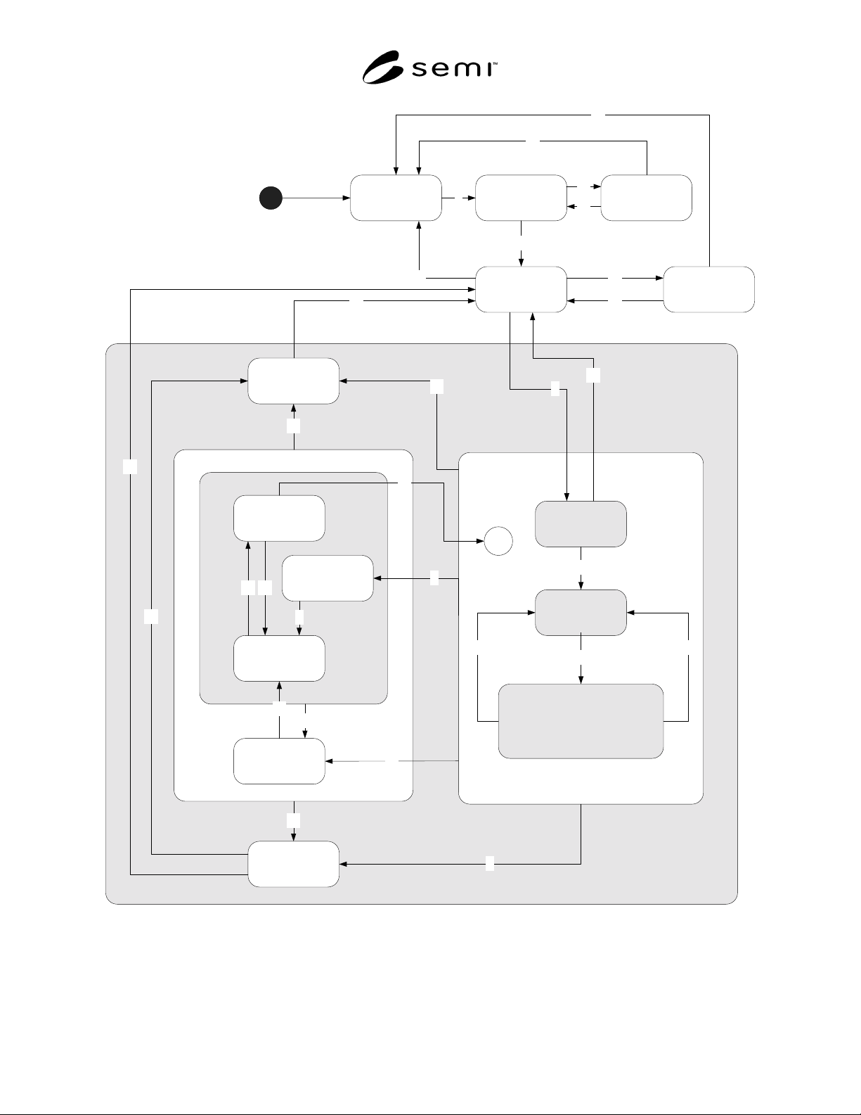
SEMI E122-0703 © SEMI 2003 3
PROCESSING ACTIVE
PAUSE
PROCESS
PAUSE
PROCESS
EXECUTING
GEM READY
PAUSED
IDLE WITH
ALARMS
ALARM
PAUSED
PAUSING
READY
ABORTING
CHECKING
SETTING UP
IDLE
INIT0
2
3
4
1
26
23
25
24
19
22
18
13 14
8
17
16
STOPPING
21
11
7
9
C*
15
20
10
65
29
INIT WITH
ALARMS
27
28
12
Figure 1
TSEM Processing State Model