semi合集-English.pdf - 第305页
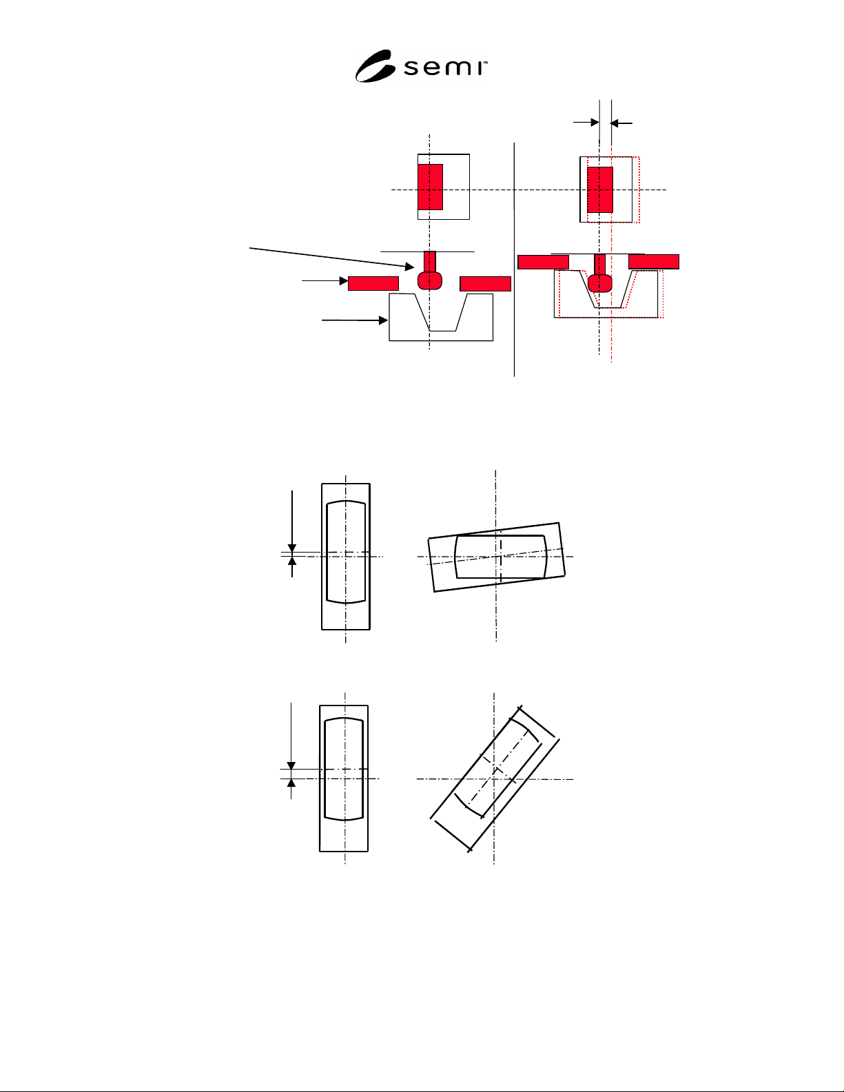
SEMI E47.1-0305 © SEMI 1997, 2005 20 Top View Cross- Section Front View FOUP door cover Latch key hole block Latch key Figure A1-1 Displacement Enabled by Flexibility Around Latch Key Hole Block Latch key can rotate full…
SEMI E47.1-0305 © SEMI 1997, 2005 19
A1-14 It is recommended that the latch key holes be maintained in the position that unlocks the FOUP door from
the FOUP ( = 0 ± 1° as defined in SEMI E62) while the FOUP is open and in the position that locks the FOUP
door to the FOUP ( = 90 ± 1°) while the FOUP is closed. One method to accomplish this is to have the FOUP
latch key hole mechanisms snap into both end points of their rotation ( = 0 ± 1° and = 90 ± 1°) using a detent
mechanism. The torque required to overcome such a detent mechanism should not exceed f30 (as defined in
SEMI E62).
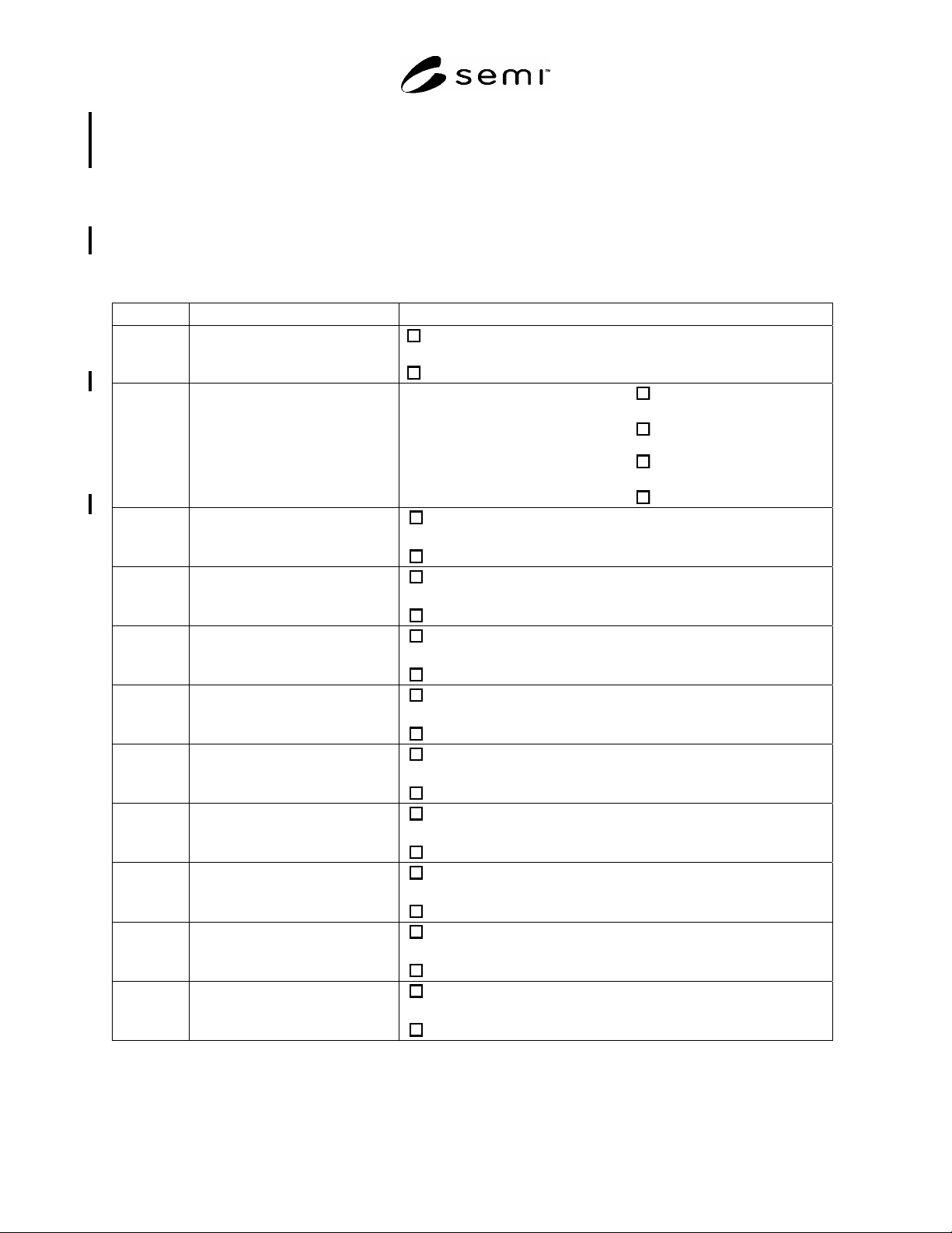
A1-15 Table A1-1 can be used for communicating the compliance of FOUPs to this standard and the options
chosen:
Table A1-1 Optional Features Checklist
Section Optional Feature Choice
4.3 carrier capacity (c)
13 wafers
or
25 wafers
6.1 full 15-mm lead in provided by 3
features that mate with kinematic
coupling pins
Primary kinematic coupling pins
yes
or
no
and
secondary kinematic coupling pins
yes
or
no
6.8 ergonomic manual handles
yes
or
no
6.9 side fork-lift flanges
yes
or
no
6.9 3 kinematic grooves on the top
robotic handling flange
yes
or
no
6.9 rear conveyor rail
yes
or
no
6.9.1 front conveyor surface
yes
or
no
6.12 info pad A height
up (pad missing)
or
down (pad present)
6.12 info pad B height
up (pad missing)
or
down (pad present)
6.12 info pad C height
up (pad missing)
or
down (pad present)
6.12 info pad D height
up (pad missing)
or
down (pad present)
SEMI E47.1-0305 © SEMI 1997, 2005 20
Top View Cross-Section
Front View
FOUP door cover
Latch key hole block
Latch key
Figure A1-1
Displacement Enabled by Flexibility Around Latch Key Hole Block
Latch key can rotate full 90°
Latch key rotation stops before 90°
Figure A1-2
Need for Latch Key Hole Flexibility
SEMI E47.1-0305 © SEMI 1997, 2005 21
RELATED INFORMATION 1
NOTICE: This related information is not an official part of SEMI E47.1, and it is not intended to modify or supercede the
official standard. This information was inserted by the North America Physical Interfaces and Carriers Committee to alert the
readers to potential changes to this provisional standard.
R1-1 A revision ballot will be submitted to require the same bottom carrier ID label area as in SEMI E1.9.
R1-2 A revision ballot will be submitted to increase the maximum thickness of the top robotic flange by 3 mm.
R1-3 A design exists for a FOUP and adapter mechanism that holds only one wafer and is supposed to comply with
SEMI E47.1. A new activity to standardize a “One Wafer FOUP” is being considered.
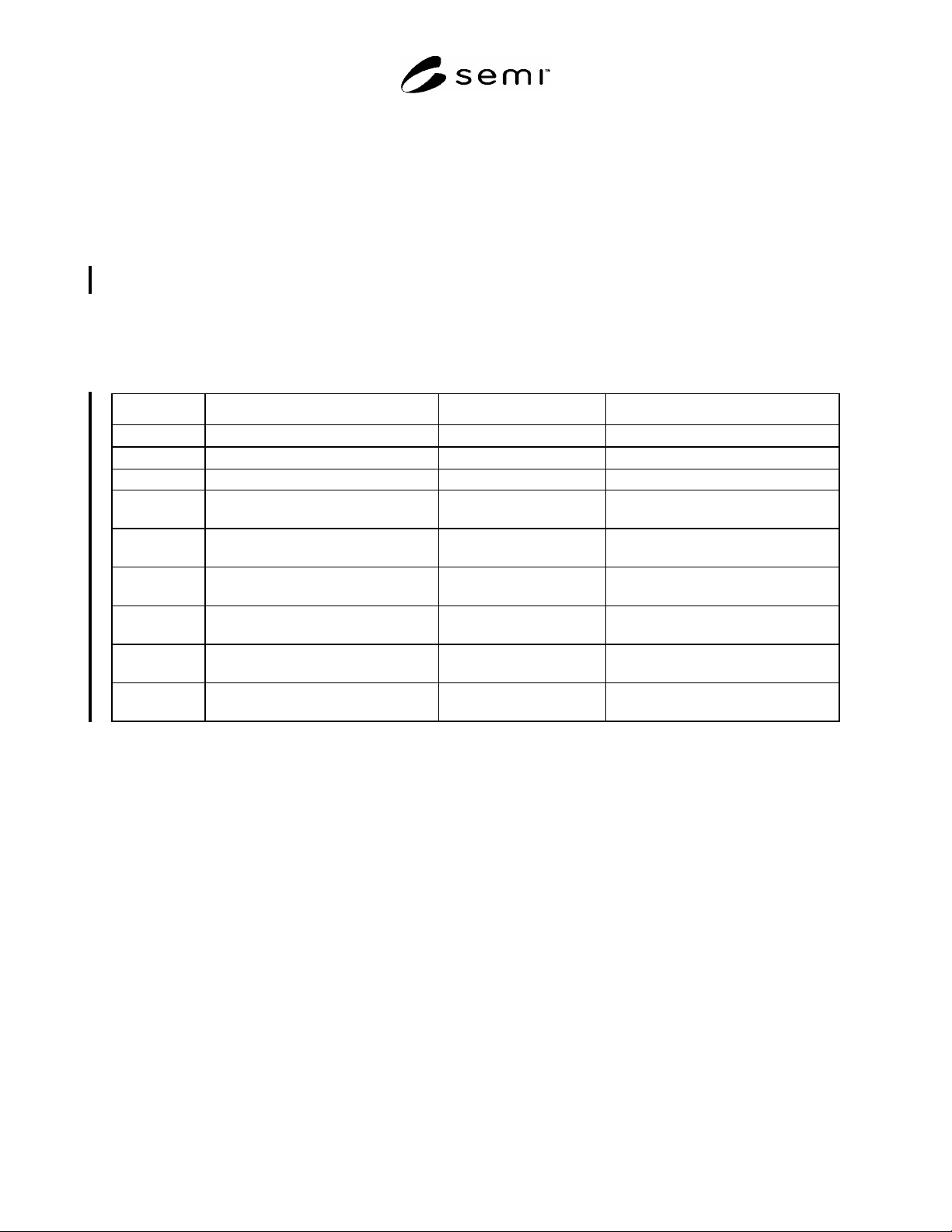
R1-4 Alternate Conveyor Features may be incorporated into FOUPs. One example is a rear conveyor groove. A
Rear Conveyor Groove is defined as below. This design, and/or the application of this design in AMHS systems
may be protected by one or more patents.
Table R1-1
Symbol Used Value Specified Datum Measured From Feature Measured To
k
17.5 2.5
conveyor groove centerline conveyor groove lead in
k
3 1
conveyor groove centerline conveyor groove lead in
R70k
0.25 mm (0.010 in.) maximum not applicable conveyor groove concave corners
R71k
0.5 mm 0.25mm
(0.02 0.01 in.)
not applicable conveyor groove convex corners
X251k
132.0 1mm
(5.31 0.04 in.)
bilateral datum plane beginning of conveyor groove lead in
Y240k
158.0 0 .5mm
(6.142 0.020 in.)
facial datum plane conveyor groove side closest to facial
datum plane
Y241k
8.50 0.25mm
(0.335 0.0 in.)
conveyor groove side
closest to facial datum plane
conveyor groove side furthest from
facial datum plane
Z314k
5.00 0.25mm
(0.236 0.010 in.)
horizontal datum plane top surface of conveyor groove
Z315k
1.3 0.5mm
(0.052 0.020 in.)
top surface of conveyor
groove
beginning of conveyor groove lead in
radius