semi合集-English.pdf - 第3289页
SEMI E130-1104 © SEMI 2003, 2004 3 6 Conventions 6.1 Remote Command Parameter Table Definitions 6.1.1 The table below p rovides an example of the t ables used to li st and describe arguments for se rvices or remote comma…

SEMI E130-1104 © SEMI 2003, 2004 2
SEMI M21 ― Specification for Assigning Addresses to
Rectangular Elements in a Cartesian Array
4.2 IEEE Standards
1
IEEE 754-1985 – IEEE Standard for Binary Floating-
Point Arithmetic
4.3 Other Documents
Harel, D., “Statechart: A Visual Formalism for
Complex Systems”, Science of Computer Programming
8 (1987) 231-274.
NOTICE: Unless otherwise indicated, all documents
cited shall be the latest published versions.
5 Terminology
5.1 Definitions
5.1.1 alignment — a procedure in which a coordinate
system is established on a substrate.
5.1.2 cassette — a physical object containing one or
more substrate locations. See SEMI E87.
5.1.3 chuck — the primary stage for processing a
substrate.
5.1.4 column — synonymous with the term “X-
coordinate”. Columns increase along the X axis.
5.1.5 die — 1. A field sub-unit. 2. An area of substrate
that contains the device being manufactured.
5.1.6 fiducial – flat or notch in the physical substrate
used to identify the substrate orientation.
5.1.7 inker — a resource of the prober. The
electromechanical units to put ink mark on die.
5.1.8 load — 1. Move a substrate onto a substrate
location. 2. Move a carrier onto the equipment.
5.1.9 marking — the process of the prober that
deposits an ink mark on a die using the inker.
5.1.10 pre-align – set up a substrate to be processed on
the chuck. The equipment may have a separate stage
for performing the pre-align function.
5.1.11 probe card — the electromechanical interface
necessary to enable temporary electrical contact
between the substrate to be tested and the tester
resource. May consist of multiple components.
5.1.12 pipeline – an equipment configuration
consisting of multiple stages through which the
equipment sequences material in succession.
1 Institute of Electrical and Electronics Engineers, IEEE Operations
Center, 445 Hoes Lane, P.O. Box 1331, Piscataway, New Jersey
08855-1331, USA. Telephone: 732.981.0060; Fax: 732.981.1721,
Website: www.ieee.org
5.1.13 row — synonymous with the term “Y-
coordinate”. Rows increase along the Y axis.
5.1.14 stage – a general term for a substrate location
that serves a specific function such as pre-align or
chuck.
5.1.15 state — 1. A static set of conditions. If the
conditions are met, the state is current (SEMI E30). 2.
A state reacts predictably to specific stimuli.
5.1.16 substrate — 1. The basic unit of material,
processed by PSEM300 equipment such as wafers.
5.1.17 unload — 1. Remove a substrate from a
substrate location. 2. Remove a carrier from the
equipment.
5.1.18 X axis — the X axis is the horizontal axis from
left to right when the substrate is rotated according to
Orientation.
5.1.19 Y axis — the Y axis is the vertical axis from
bottom to top when the substrate is rotated according to
Orientation.
SEMI E130-1104 © SEMI 2003, 2004 3
6 Conventions
6.1 Remote Command Parameter Table Definitions
6.1.1 The table below provides an example of the tables used to list and describe arguments for services or remote
commands defined in this specification.
Parameter Req/Ind Rsp/Cnf Form Comment
(see below) (see below)
6.1.2 Parameter – Specifies the name of the parameter.
6.1.3 Req/Ind – Specifies relationship of the parameter for the command request or indication message. See below
table for codes used.
6.1.4 Rsp/Cnf – Specifies relationship of the parameter for the command response or confirmation message. See
below table for codes used.
6.1.5 Form – Specifies the data type of the parameter. Data types are as defined in the SEMI compilation of terms
or are included in this specification. Specific representation of the data types will depend on and be defined by the
communications protocol and data format adjunct specification.
6.1.6 The following codes appear in the Req/Ind and Rsp/Cnf columns to define how each parameter is used in each
direction:
M Mandatory Parameter – Must be given a valid value.
C Conditional Parameter – May be defined in some circumstances and undefined in others. Whether a
value is given may be completely optional or may depend on the value of the other parameter.
U User-Defined Parameter
- The parameter is not used.
= (for response only) Indicates that the value of this parameter in the response must match that in the
primary (if defined).
7 Requirements
7.1 Following sections in this document, except such supplementary descriptions as Related Information, are
requirements of this specification.
8 State Model
8.1 The purpose is to define the equipment-specific processing state model to portray the expected operational
states of the equipment to enable host tracking and control in place of a local operator. Process Job Management
standard (SEMI E40) is part of the required behavior of this document as described in Section 9. For additional
description of this behavior see Section 10 or See the actual standard, SEMI E40.
8.1.1 The Process State model tracks the state of the equipment with regard to its ability to perform processing on a
substrate. The Process State model is used to inform the host when a substrate is loaded on the main chuck and has
been properly setup for processing.
8.1.2 It is expected that the prober will be preparing a substrate to be loaded on the main chuck while the host is
processing an existing substrate on the main chuck. This concurrent activity does not impact the host’s ability to
process the existing substrate and therefore does not cause a change in the Process State model. The standard for
Substrate Tracking (SEMI E90) is used for tracking substrates between individual substrate locations.
8.1.3 The processing state model in this document is required for implementing a PSEM300-compliant prober, in
addition to the required state models in the related standards. A state model consists of a state model diagram, state
definitions, and a state transition table. A state model represents the host’s view of the prober, but not necessarily
the actual prober operations. All PSEM300 state model transitions shall be mapped sequentially into the actual
SEMI E130-1104 © SEMI 2003, 2004 4
equipment events that satisfy the requirements of those transitions. In certain implementations, the prober may enter
a state and has already satisfied all of the conditions required by the PSEM300 state model for transition to another
state. In this situation, the prober makes the required transition without any additional actions.
8.1.4 Some equipment may need to include additional states. However, any additional states must not change the
PSEM300-defined state transitions. All expected transitions between PSEM300 states must occur.
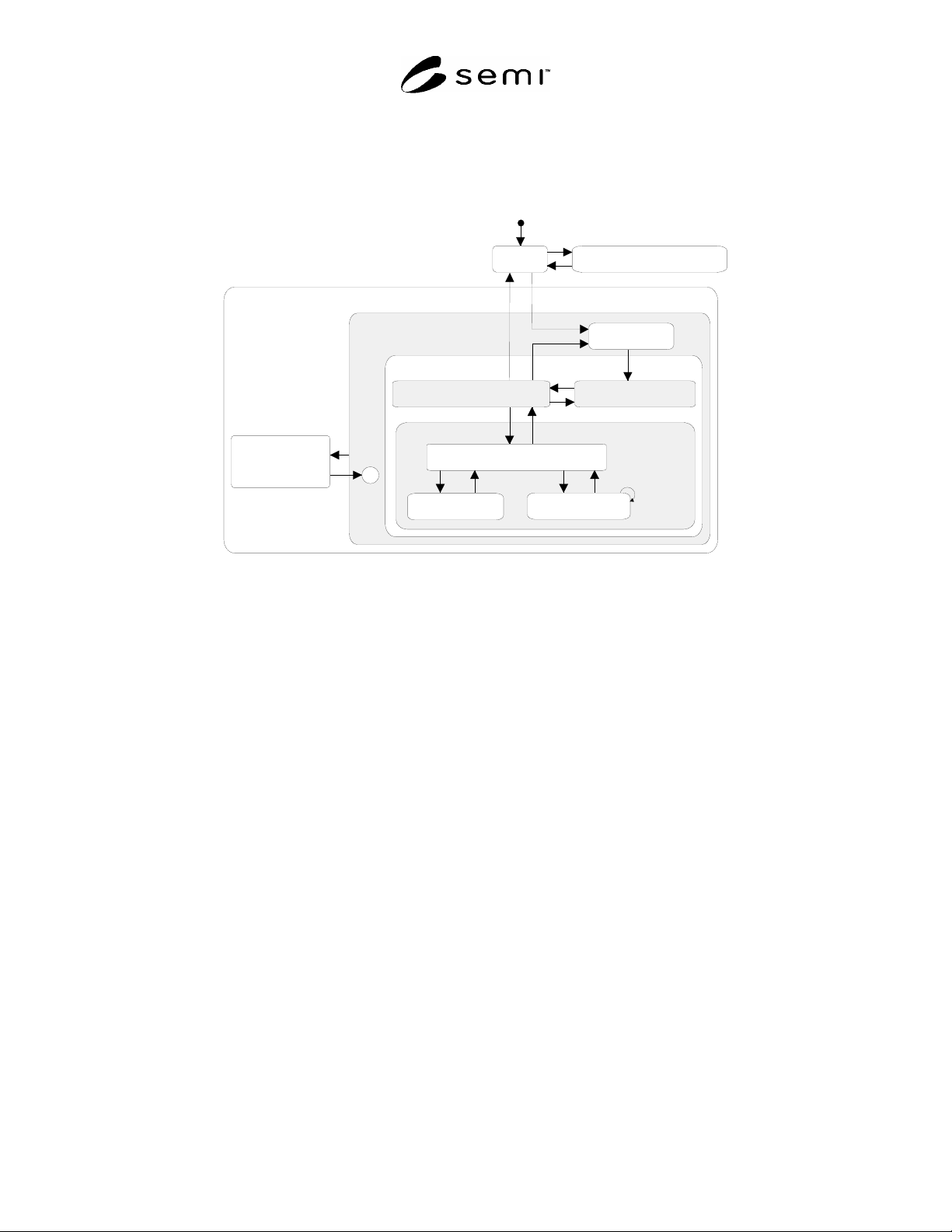
PROCESS
EXECUTING
PROCESSING
BLOCKED
3
C
16
15
4
5
SUBSTRATE
LOADED
6
8
10
9
11
12
13
1
2
IDLE
SETTING UP
AWAITING COMMAND
HANDLING MATERIAL
SERVICE TASK
MOVING XYZ
AWAITING LOAD
7
IDLE WITH ALARMS
PROCESSING ACTIVE
17
18
14
Figure 1
PSEM Process State Model Diagram
8.1.5 Description of Prober Processing States
8.1.5.1 AWAITING COMMAND (SUBSTRATE LOADED Sub-state) — A substrate on the main chuck is ready for
processing. The prober is ready to receive an instruction from the host.
8.1.5.2 AWAITING LOAD (EXECUTING Sub-state) — At least one Process Job is in the PROCESSING state. No
substrate is loaded on the main chuck. The prober is waiting for a host command to load a substrate.
8.1.5.3 EXECUTING (PROCESS Sub-state) — One of the following conditions exists: A) At least one Process Job
is in the PROCESSING state and the prober is processing material as directed by the host. B) A single Process Job
is active in either the STOPPING or ABORTING state and the prober is removing material.
8.1.5.4 IDLE — No Process Jobs are in the ACTIVE state and the processing resource is available without alarms.
8.1.5.5 HANDLING MATERIAL (EXECUTING Sub-state) — The prober is loading a substrate, unloading a
substrate, or a combined action of loading and unloading substrates on the main chuck. When loading a substrate
onto the main chuck, the HANDLING MATERIAL state is maintained until all preconditioning tasks (i.e. aligning,
profiling, etc.) are completed and the substrate is ready for processing. If a condition arises where the substrate on a
chuck must be re-aligned, the HANDLING MATERIAL state is active until the alignment task has completed.
8.1.5.6 MOVING XYZ (SUBSTRATE LOADED Sub-state) — The prober is executing a move command. This state
is maintained until the move is complete. This includes motion in the z-axis. When this state is exited, the target
unit(s) on the substrate is in position to be processed.
8.1.5.7 PROCESS (PROCESSING ACTIVE Sub-state) — This state is the parent of those sub-states that refer to the
preparation and execution of a process job.
8.1.5.8 PROCESSING ACTIVE — The state in which at least one Process Job is active.
8.1.5.9 PROCESSING BLOCKED — The processing resource is not available for processing.
8.1.5.10 SETTING UP (PROCESS Sub-state) — A single ACTIVE Process Job is in the SETTING UP state.