semi合集-English.pdf - 第3456页
SEMI E134-0305 © SEMI 2004, 2005 9 of the event. Suc h variables can include process data s uch as pressures, temperatures, or voltages, or context data such as job related dat a, recipe ID’s, eq uipment config uration o…
SEMI E134-0305 © SEMI 2004, 2005 8
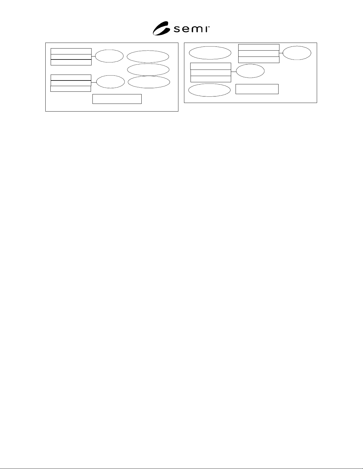
Parameter A
Event A
Event B
Exception A
Exception B
Exception C
Parameter B
Parameter C
Parameter D
Parameter F
Parameter G
Utilization Data Collection Plan
DCP Buffering Interval
= 5 minutes
Trace A
Exception J
Exception B
Parameter L
Parameter X
Parameter T
Process Data Collection Plan
DCP Buffering
Interval = disabled
Parameter A
Event Z
Parameter B
Parameter C
Figure 5
Data Collection Schemes with Different Objectives
7.1.4 It is possible for consumers to submit data collection requests which, when executing together, significantly
tax the equipment’s computing resources. When the equipment detects that this is occurring, it should be able to
provide a warning to consumers that a performance threshold is being reached. Consumers can respond to these
warnings by adjusting or disabling the active data collection requests. In the worst case, if the equipment determines
that continuing to operate under degraded performance conditions may seriously jeopardize its ability to perform its
intended function, the equipment can terminate all data collection activity.
7.1.5 This specification describes the concepts and behaviors necessary to facilitate these capabilities on equipment.
8 Overview
8.1 Data Collection Concepts
8.1.1 This specification allows consumers to describe a set of data in which they are interested, and to ask the
equipment to send only that data off-tool, according to a buffering policy specified by the consumer. The types of
data that are supported by this specification are described in the following sections.
8.2 Trace Data
8.2.1 Trace data allows data acquisition consumers to request the collection of data values that are continuously
changing, or that change frequently such as pressure, temperature, RF power, magnetic field strength, or individual
actuator state changes, etc. This document defines a mechanism for specifying when trace data collection begins
and ends, what the collection frequency is, and what variables are to be collected in the trace (see Section 11.1.5).
8.2.2 This specification defines a mechanism for specifying when to start tracing (see Section 11.1.5.6):
On the occurrence of a specific event or exception from a set of possible events and exceptions
As soon as enabled
8.2.3 This specification defines a mechanism for specifying when to stop tracing (see Section 11.1.5.7):
On the occurrence of a specific event or exception from a set of possible events and exceptions
After a specified number of collection results have been accumulated
As soon as disabled
8.2.4 This specification defines a mechanism for identifying parameters to be included in trace data collection (see
Section 11.1.9). Consumers can use any naming convention supported by the equipment, provided that such
conventions can support the concept of a parameter source and a parameter name represented as text fields.
8.2.5 This specification defines a mechanism to support on-tool buffering, allowing trace reports containing many
collection results to be sent off-tool at a regular interval (see Sections 11.1.2.3 and 11.1.5.3).
8.3 Events
8.3.1 Events allow data acquisition consumers to determine when a subsystem, process job, sensor/actuator, or
other modeled system undergoes a state transition. Events may have data variables associated with the occurrence

SEMI E134-0305 © SEMI 2004, 2005 9
of the event. Such variables can include process data such as pressures, temperatures, or voltages, or context data
such as job related data, recipe ID’s, equipment configuration or offset values. Typical consumers need to be able to
specify which variables are to be provided with the event when it is communicated.
8.3.2 This specification defines a mechanism for identifying events and parameters to be included in data collection.
Consumers can use any naming convention that is supported by the equipment, provided that such convention can
support the concept of event sources and event id’s, and parameter sources and parameter names, each represented
as text fields (see Sections 11.1.3 and 14.1.3).
8.3.3 This specification defines a mechanism to support on-tool buffering of events, allowing a periodic report of
any events that occurred during a specified interval to be sent off-tool (see Section 11.1.2.3).
8.4 Exceptions
8.4.1 Exceptions allow data acquisition consumers to know when errors, warnings, or alarms occur on the
equipment. These may indicate conditions which affect processing, safety, or the proper operation of the equipment.
Exceptions may have data variables associated with the occurrence of the exception. The list of these variables will
be fixed by the equipment implementation.
8.4.2 This specification defines a mechanism for identifying exceptions to be included in data collection.
Consumers can use any naming convention that is supported by the equipment, provided that such convention can
support the concept of exception sources and exception id’s, each represented as text fields (see Sections 11.1.4 and
14.1.4).
8.4.3 This specification defines a mechanism to support on-tool buffering of exceptions, allowing a periodic report
of any exceptions that occurred during a specified interval to be sent off-tool (see Section 11.1.2.3).
8.5 Data Collection Plans
8.5.1 A data collection plan assembles all of the related trace, event, and exception data that may be required for a
specific consumer’s purpose. For example, a consumer interested in tracking the utilization of the equipment may
only be interested in specific events that mark actions the equipment takes that indicate how it is being exercised,
certain exceptions that may interrupt the equipment, and no trace data. Such a data collection plan might be in effect
at all times the equipment is running.
8.5.2 A fault detection consumer may be interested in trace, event, and exception data for a specific processing run,
and may change the collected data depending on the recipe used. Such data collection plans may only be in effect
while specific jobs are in process on the equipment. Coordination of data collection plan activation with job activity
on the equipment is the consumers’ responsibility, and is not specified in this document.
8.5.3 This document specifies a mechanism for consumers to define one or more data collection plans off-tool and
submit those definitions to the equipment (see Sections 9.1.2.2 and 11). This document specifies a mechanism for
determining what plans have been created on the equipment, how they are defined, and whether or not they are
activated (see Sections 9.1.2.3, 9.1.2.4, and 9.1.2.6). A mechanism for activating, deactivating, and deleting
individual plans is also specified (see Sections 9.1.2.5, 9.1.2.7, and 9.1.2.8). The required behavior of data
collection plans is specified in Section 12.
8.6 Equipment Operational Performance Monitoring
8.6.1 It is possible for consumers to submit data collection requests which, when executing together, significantly
tax the equipment’s computing resources, in addition to any load placed on the equipment by jobs that are in
progress. This document specifies a mechanism for notifying all DCP consumers when such a condition has been
detected, to identify what DCPs and jobs are in progress at the time, and to identify the specific equipment
components that are being adversely affected (see Sections 9.1.2.11, 13, 15.1.5, and 15.1.6).
8.7 Ad-hoc Data Requests
8.7.1 Ad-hoc data requests are used in cases where the value of some data items is needed at a specific instance in
time, and which may not be associated with a specific event or exception. As a simple example, consider an
application that monitors equipment utilization. Such an application may have an initialization procedure that
includes determining the current state of each monitored component on the equipment. Without a mechanism for
requesting this information at initialization, the application would instead have to wait for state change events from
each component before it could determine their state. This may not be acceptable if the application provides a
SEMI E134-0305 © SEMI 2004, 2005 10
visualization of the equipment to an end user who relies on the application to call attention to problem conditions on
the equipment.
8.7.2 This document specifies a mechanism for consumers to issue ad-hoc requests for data in order to support these
uses, through the GetObjectInstanceIds and GetParameterValue operations of the DataCollectionManager interface
(see Sections 9.1.2.9 and 9.1.2.10).
9 Data Collection Plan Management
9.1 DataCollectionManager Interface
9.1.1 Figure 6 shows the interface used to manage data collection plans on the equipment, as well as making ad-hoc
requests for specific data, and for determining the current performance conditions on the equipment.
DefinePlan(in newPlan : DataCollectionPlan) : DCPDefined
GetDefinedPlanIds() : DCPDefined[]
GetPlanDefinition(in dc pId : String) : DataCollec tionPlan
Ac tivatePlan(in dc pI d : String) : D C PAct ivated
GetActivePlanIds() : DCPActivated[]
DeactivatePlan(in dcpId : String, in terminate : boolean) : DCPDeactivated
DeletePlan(in dcpId : DCPIdentifier) : DCPDeleted
GetParameterValues(in parameterRequest : ParameterRequest[]) : ParameterValu
e
GetObjT ypeIns tanceIds (in request : ObjT ypeReques t[ ] ) : ObjTypeResult[]
GetCurrentPerformanceStatus() : PerformanceStatus
«interface»
DataCollectionManager
Figure 6
The Data CollectionManager Interface
9.1.2 DataCollectionManager — The DataCollectionManager interface provides consumers with operations to
manage data collection activities on the equipment. The interface provides operations for consumers to submit new
DCP’s, activate and deactivate them, look up existing plans, and delete defined plans. The DataCollectionManager
interface also provides operations to request the current equipment performance status as well as requesting ad-hoc
data on demand.
9.1.2.1 DataCollectionManager Operations
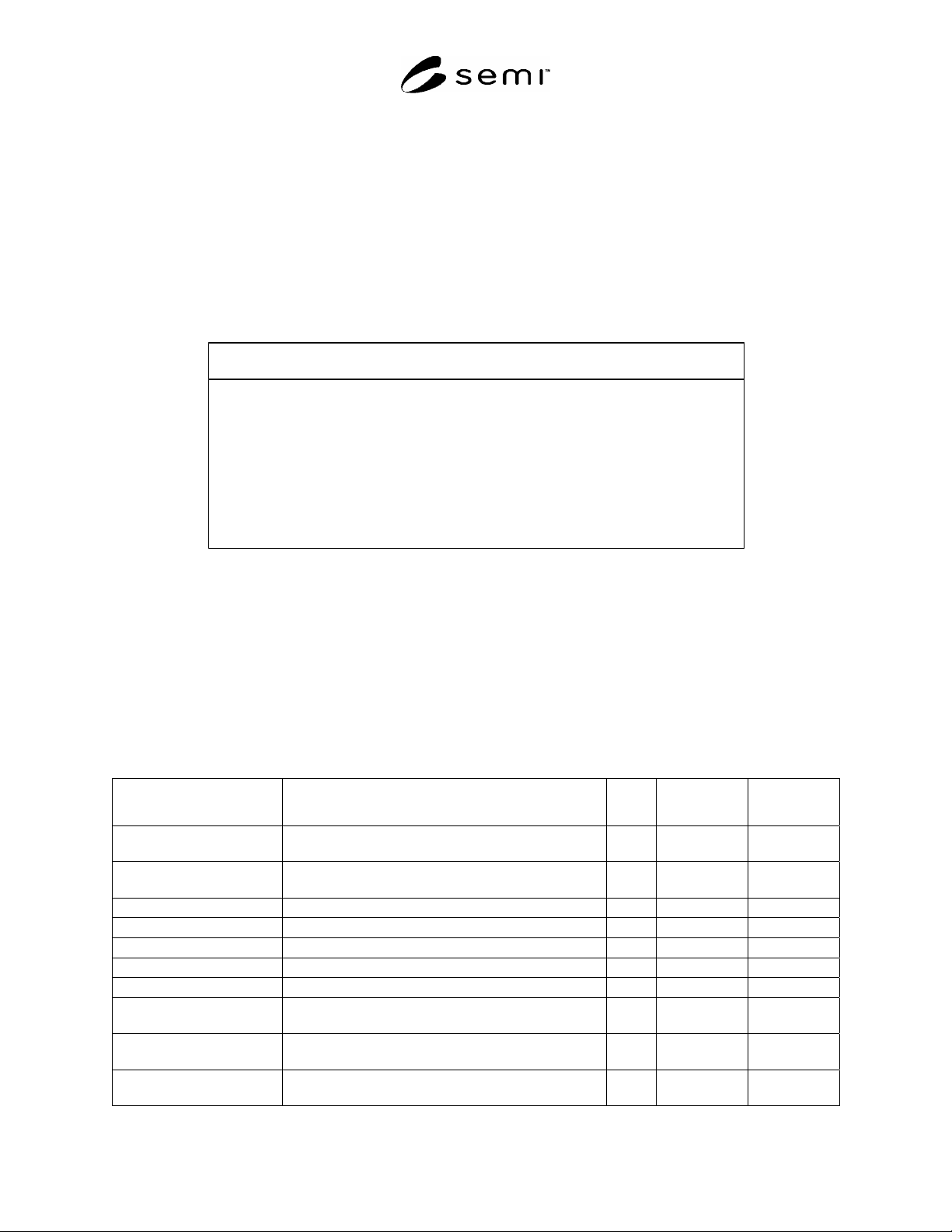
Table 5 DataCollectionManager Operation Definition
Operation Description Type Requestor/Sen
der
Responder/Rec
eiver
DefinePlan Submit a new plan definition to the equipment for
validation.
RR Consumer Equipment
GetDefinedPlanIds Retrieve a list of all valid DCP id’s known to the
equipment.
RR Consumer Equipment
GetPlanDefinition Retrieve the definition of a specific DCP. RR Consumer Equipment
ActivatePlan Activate a defined DCP. RR Consumer Equipment
GetActivePlanIds Retrieve a list of all currently active DCPs. RR Consumer Equipment
DeactivatePlan Deactivate an active DCP. RR Consumer Equipment
DeletePlan Delete a DCP. RR Consumer Equipment
GetParameterValues Retrieve the most recent values of one or more
Parameters.
RR Consumer Equipment
GetObjTypeInstanceIds Retrieve a current list of the unique instance id’s for one
or more E39 ObjTypes.
RR Consumer Equipment
GetCurrentPerformanceStatu
s
Retrieve the most recent equipment performance status. RR Consumer Equipment