semi合集-English.pdf - 第3580页
SEMI E139-0705 © SEMI 2005 4 details are not specified, but the required function of the interface is defined. This will be furt her explained later in the document. 2.3 In summ ary, these are the interfaces th at are sp…
SEMI E139-0705 © SEMI 2005 3
1 Purpose
1.1 The purpose of this specification is to specify the cooperative interaction between the Factory Information &
Control System (FICS) and the equipment to manage the specifications of equipment processing (for instance,
equipment recipes).
1.2 There are six primary elements that must be supported to achieve this purpose:
On-tool & Off-tool Recipe Management — Support the management of multi-part recipes within the equipment
as well as at the FICS level without the requirement that these management applications be integrated.
Recipe Integrity — Guarantee that the recipes that define process execution on a piece of equipment are the
same as those intended for that use within the FICS.
Process Integrity — Ensure that all configuration values/settings of the tool that can be changed by the user and
which affect the process outcome can be managed by the host within the context of a process job.
Adjustable Parameter Definition — Support the definition of recipe parameters to be used by other SEMI
standards (for example SEMI E40) to adjust the parameter values in a consistent manner across all equipment.
On-tool & Off-tool Recipe Creation & Editing — Define a consistent interaction protocol between the FICS and
the systems(s) that support recipe creation/editing functionality.
Information Accessibility — Make key information about the recipes visible to the FICS.
1.2.1 See §7 for a discussion of how the purpose is achieved. A summary is contained in ¶7.13
2 Scope
2.1 This specification defines concepts, behavior, and services to support automated management of equipment
recipes and related process definition elements within a semiconductor factory. It addresses the mechanisms for
interaction between semiconductor equipment, recipe editors, and the Factory Information and Control System
(FICS).
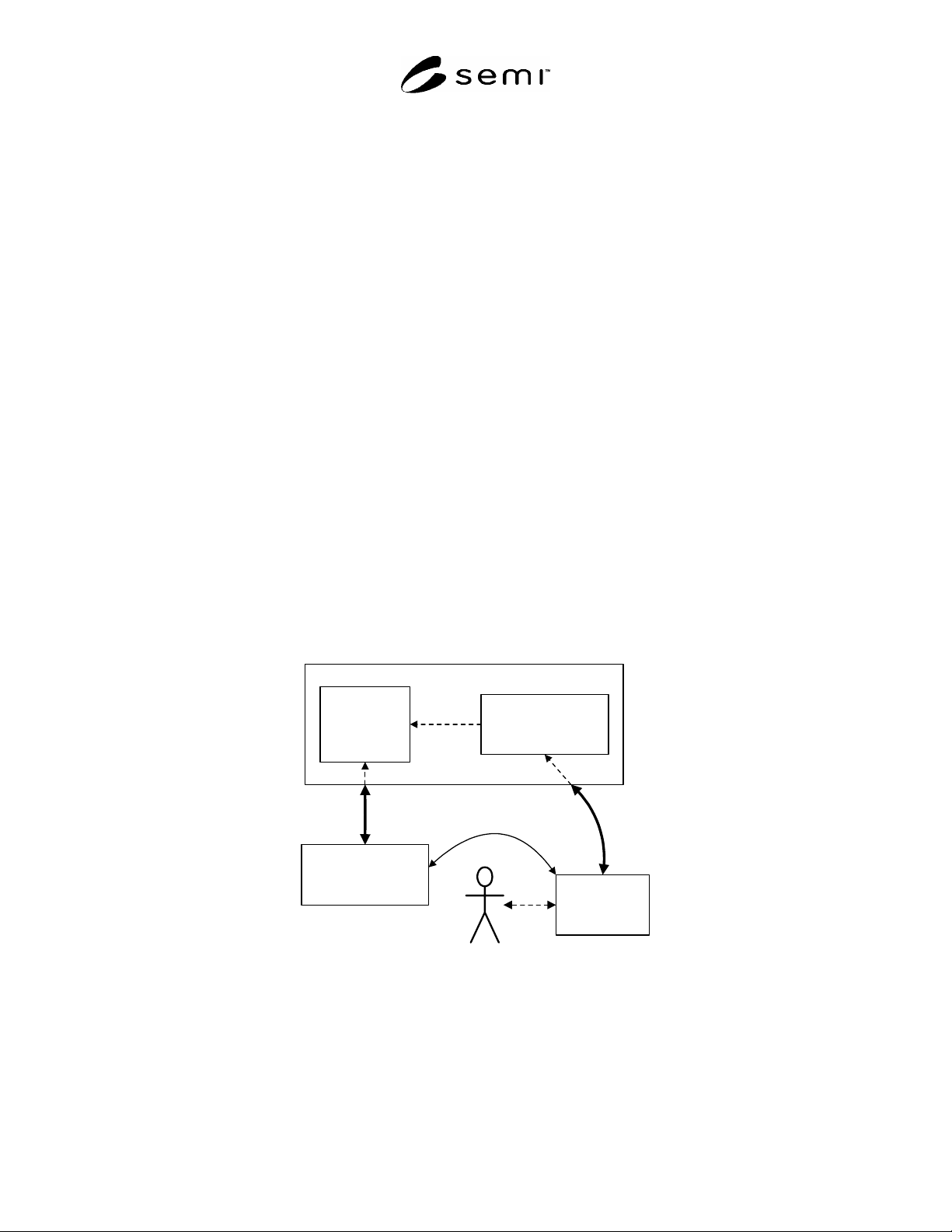
Station
Controller
Equipment
PDE/Recipe
Management
Factory Information and
Control System (FICS)
PDE/Recipe
Editor
Figure 1
RaP Subject Matter
2.2 Figure 1 illustrates the interactions that are addressed in this specification. The thicker arrows are fully
specified interfaces. The dashed arrows are completely unspecified interfaces that are shown here to aid in
understanding the concepts of recipe management. The thinner arrow represents a partially specified interface
(between equipment and recipe editor) that may be proprietary to the supplier. For this last interface, the messaging

SEMI E139-0705 © SEMI 2005 4
details are not specified, but the required function of the interface is defined. This will be further explained later in
the document.
2.3 In summary, these are the interfaces that are specified in this document:
FICS Equipment – full messaging services
FICS PDE/Recipe Editor – full messaging services
Equipment PDE/Recipe Editor – functional requirements only
NOTICE: This standard does not purport to address safety issues, if any, associated with its use. It is the
responsibility of the users of this standard to establish appropriate safety and health practices and determine the
applicability of regulatory or other limitations prior to use.
3 Limitations
3.1 The following items are out of scope and are not specified in this document:
The content or format of the PDEbody.
The message format and communication details of message services.
How PDEs are used or executed within the equipment.
How the FICS initiates execution of PDEs within the equipment.
How and when the parameter values are communicated to the equipment.
How data is collected to document what PDEs and parameter values were used in a specific situation.
The interactions between a human user and the PDE/Recipe Editor.
Design of FICS applications (for example, Station Controller and PDE/Recipe Manager as shown in Figure 1).
These applications are shown to enhance the clarity of the content of this specification.
4 Referenced Standards and Documents
4.1 SEMI Standards
1
SEMI E5 — SEMI Equipment Communication Standard 2 (SECS-II)
SEMI E30 — Generic Model for Communications and Control of SEMI Equipment (GEM)
SEMI E40 — Standard for Process Job Management (PJM)
SEMI E120 — Common Equipment Module (CEM)
4.2 ISO Standards
2
uuid: ISO/IEC 11578:1996 Information technology - Open Systems Interconnection – Remote Procedure Call
(RPC), http://www.iso.ch/cate/d2229.htm.
4.3 OMG Standards
3
Unified Modeling Language (UML) Specification, Version 1.4, OMG Specification 01-09-67, available from
http://www.omg.org/technology/documents/modeling_spec_catalog.htm.
NOTICE: Unless otherwise indicated, all documents cited shall be the latest published versions.
1 Semiconductor Equipment and Materials International (SEMI), 3081 Zanker Road, San Jose, CA 95134, 408.943.6900, FAX 408.428.9600
2 International Organization for Standardization, ISO Central Secretariat, 1, rue de Varembé, Case postale 56, CH-1211 Geneva 20, Switzerland.
Telephone: 41.22.749.01.11; Fax: 41.22.733.34.30, Website: /www.iso.ch
3 Object Management Group, Inc., 250 First Ave. Suite 100, Needham Mass. 02494, Telephone: 781.444.0404; Fax: 781.444.0320, Website:
www.omg.org

SEMI E139-0705 © SEMI 2005 5
5 Terminology
5.1 SEMI Compilation of Terms
5.1.1 Definitions or descriptions of many of the terms used in this specification can be found in the SEMI
Compilation of Terms, available on the SEMI web site,
http://www.semi.org/; and in the OMG UML specification.
For terms related to object models, the definition from the OMG UML specification has precedence.
5.2 Abbreviations and Acronyms
5.2.1 FICS — Factory Information & Control System
5.2.2 PDE — Process Definition Element
5.2.3 RaP — Recipe and Parameter Management – this specification.
5.2.4 UML — Unified Modeling Language
5.3 Definitions
5.3.1 Checksum — a single unique value calculated from a sequence of data (a file, a string, etc.) that uniquely
identifies that data. It is sometimes called a “digital fingerprint” or a “message digest”. No two (different)
sequences of data are likely to have the same checksum. Therefore, a checksum can be used to check data integrity.
A typical method is to 1) calculate the checksum for a data sequence; 2) deliver that data sequence and its checksum
value to a separate entity; 3) the receiving entity recalculates the checksum value and compares it with the original
from the sender. If the checksums are the same, the receiver is assured that the data has not been modified or
corrupted.
5.3.2 Factory Information and Control System (FICS) — the software system that controls the operation of the
factory and its equipment. It may include such components commonly referred to as the MES, Station Controllers,
Recipe Managers, etc.
5.3.3 Module Parameter — settings that affect processing on an equipment module (typically a Process Module).
For a Process Module, the Module Parameters might represent temperatures, pressures, flow rates, etc. An
equipment recipe typically manipulates Module Parameters to accomplish its purpose.
5.3.4 PDE (Process Definition Element) — an executable specification of an activity or process on an equipment.
The recipe for a particular equipment activity may consist of multiple PDEs. A PDE is the smallest process
definition unit that can be individually managed with FICS participation or knowledge. Each PDE includes a
PDEheader and a PDEbody.
5.3.5 PDEbody — the executable portion of a Process Definition Element. The PDEbody is typically contained
within the PDE construct. In some cases, a PDEbody may exist as a separate entity, but it is always exclusively
related to its PDE.
5.3.6 PDEeditor — a software system that provides the ability to create, delete, and modify a PDE. A PDEeditor
may exist as a subsystem of an equipment or as a standalone system provided either by the manufacturer of the
equipment or a third party.
5.3.7
PDEheader — the descriptive portion of a Process Definition Element. The PDEheader is a collection of
information related to a PDEbody. This information is sufficient to manage and utilize the PDE without accessing
its PDEbody.
5.3.8 uuid — universally unique identifier. This 128-bit field (often represented as a 36-character string) is
calculated according to the standard ISO/IEC 11578:1996 – Remote Procedure Call (RPC). The field is guaranteed
to be unique over all space and time. The uniqueness holds even though the uuids are created independently by
separate entities.
5.3.9 Variable Parameter — a formally defined variable (setting) defined in the body of a recipe, permitting the
actual value to be supplied externally.