semi合集-English.pdf - 第3807页
SEMI F13-1101 © SEMI 199 3, 2001 1 SEMI F13-1101 GUIDE FOR GA S SOURCE CONTROL EQUIPM ENT This g u ide w as technica ll y a pproved by the Global Facilitie s Committee and is t he direct responsibility of the North A mer…
SEMI F12-0998 © SEMI 1993, 19985
RELATED INFORMATION 1
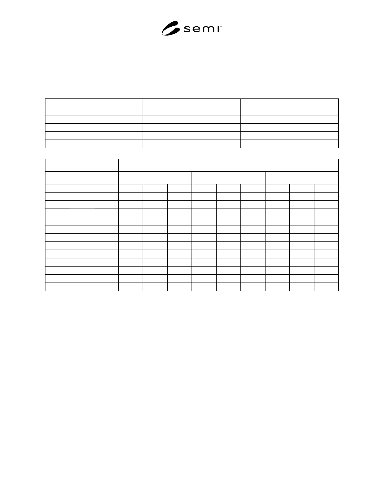
SAMPLE TEST DATA SHEET
NOTE: This related information is not an official part of SEMI F12 and is not intended to modify or supercede the official test
method. It has been derived from industry specifications. Publication was authorized by full letter ballot procedures.
Determination of the suitability of the material is solely the responsibility of the user.
Test Date: Operator: Test Facility:
Tube Manufacturer: Fitting Manufacturer:
Tube O.D.: Fitting Type:
Tube Wall Thickness: Fitting Size:
Tube P/N: Fitting P/N:
Tube Material: Fitting Material:
Amount of Leakage: Bubbles per Minute
Test Temperature 75°C 100°C 125°C
Test Sample 123123123
Proof Test
Heat Cycle xxxx xxx xxxx xxx xxxx xxx xxxx xxx xxxx
1st time
2nd time
3rd time
4th time
5th time
6th time
7th time
8th time
9th time
10th time
NOTICE: These standards do not purport to address safety issues, if any, associated with their use. It is the
responsibility of the user of these standards to establish appropriate safety and health practices and determine the
applicability of regulatory limitations prior to use. SEMI makes no warranties or representations as to the suitability
of the standards set forth herein for any particular application. The determination of the suitability of the standard is
solely the responsibility of the user. Users are cautioned to refer to manufacturer’s instructions, product labels,
product data sheets, and other relevant literature respecting any materials mentioned herein. These standards are
subject to change without notice.
The user’s attention is called to the possibility that compliance with this standard may require use of copyrighted
material or of an invention covered by patent rights. By publication of this standard, SEMI takes no position
respecting the validity of any patent rights or copyrights asserted in connection with any item mentioned in this
standard. Users of this standard are expressly advised that determination of any such patent rights or copyrights, and
the risk of infringement of such rights, are entirely their own responsibility.
Copyright by SEMI® (Semiconductor Equipment and Materials
International), 3081 Zanker Road, San Jose, CA 95134. Reproduction o
f
the contents in whole or in part is forbidden without express written
consent of SEMI.

SEMI F13-1101 © SEMI 1993, 20011
SEMI F13-1101
GUIDE FOR GAS SOURCE CONTROL EQUIPMENT
This guide was technically approved by the Global Facilities Committee and is the direct responsibility of the
North American Facilities Committee. Current edition approved by the North American Regional Standards
Committee on August 27, 2001. Initially available at www.semi.org September 2001; to be published
November 2001. Originally published in 1993.
1 Purpose
1.1 The purpose of this document is to provide a guide
for the design and operational requirements of gas
source control equipment which is used to control
pressure and flow from a gas cylinder to the point of
use.
2 Scope
2.1 This document describes the components and
minimum performance criteria for gas source control
equipment used with hazardous production material
(HPM) semiconductor gases. This guide also includes
recommended component functions and operating
requirements.
2.2 This standard does not purport to address safety
issues, if any, associated with its use. It is the
responsibility of the users of this standard to establish
appropriate safety health practices and determine the
applicability or regulatory limitations prior to use.
3 Related Documents
3.1 These documents should be used in the design,
fabrication, installation, and operation of gas source
control equipment.
3.2 SEMI Standards and Safety Guidelines
SEMI F1 — Specification for Leak Integrity of High-
Purity Gas Piping Systems and Components
SEMI F2 — Specification for 316L Stainless Steel
Tubing for General Purpose Semiconductor
Manufacturing Applications
SEMI F3 — Guide for Welding Stainless Steel Tubing
for Semiconductor Manufacturing Applications
SEMI F4 — Guide for Remotely Actuated Cylinder
Valves
SEMI F6 — Guide for Secondary Containment of
Hazardous Gas Piping Systems
SEMI F14 — Guide for the Design of Gas Source
Equipment Enclosures
SEMI S2 — Environmental, Health, and Safety
Guideline for Semiconductor Manufacturing Equipment
SEMI S4 — Safety Guideline for the Segregation/
Separation of Gas Cylinders Contained in Cabinets
SEMI S5 — Safety Guideline for Flow Limiting
Devices
3.3 Compressed Gas Association Documents
1
Pamphlet P-1 — Safe Handling of Compressed Gases
in Containers
Standard V-1 — Compressed Gas Cylinder Valve
Outlet and Inlet Connections
3.4 National Fire Protection Association Document
2
NFPA 704 — Identification of the Hazards of Materials
for Emergency Response
NOTE 1: Unless otherwise indicated, all documents cited
shall be the latest published versions.
4 Referenced Standards
4.1 Various codes and ordinances apply in different
municipalities. These documents must be followed for
the installation and operation of these systems. These
codes may include:
Applicable Occupancy Codes — Uniform Building
Code (UBC)
3
Article 51 — Uniform Fire Code (companion document
to above UBC)
Article 80 — Uniform Fire Code (companion document
to above UBC)
Applicable Occupancy Codes — BOCA National
Building Code
4
, BOCA National Fire Prevention Code
4
Local Ordinances — As applicable.
NOTE 2: Unless otherwise indicated, all documents cited
shall be the latest published versions.
1 Compressed Gas Association, Inc. (CGA), 1725 Jefferson Davis
Highway, Suite 1004, Arlington, VA 22202
2 National Fire Protection Association, 1 Batterymarch Park, Quincy,
MA 02269
3 International Conference of Building Officials (OCBO), 5360
Workman Mill Road, Whitter, CA 90601
4 Building Officials and Code Administrators International, Inc.
(BOCA), 4051 W. Flossmoor Road, Country Club Hills, IL 60478
SEMI F13-1101 © SEMI 1993, 2001 2
5 Terminology
5.1 automatic shut-off (ASO) — A remotely actuated
valve, preferably the cylinder valve, but possibly a
valve located close to the cylinder valve, which can
isolate the product as close to the cylinder valve as
possible. It may also be a device which attaches to the
cylinder valve stem or handle to close the valve.
5.2 compressed gas association (CGA) —
Organization that sets standards for the handling and
safe use of gases. Used in this document to refer to the
cylinder valve outlet connection for each product as
designated by the CGA.
5.3 cylinder — A pressure vessel designed for
pressures higher than 276 kPa (40 pounds per square
inch absolute) and having a circular cross section. It
does not include a portable tank, multi-unit tank car
tank, cargo tank, or tank car. It also refers to non-DOT
low pressure containers used for liquid product having
low vapor pressure.
5.4 gas source control equipment (GSCE) — Refers to
the equipment assembly beginning at the product exit
from the cylinder valve to the beginning of the
distribution piping leading to the point of use (POU).
These assemblies are usually mounted on panels and
are sometimes referred to as process panel systems.
5.5 hazardous production material (HPM) — A solid,
liquid, or gas that has a degree-of-hazard rating in
health, flammability, or reactivity of Class 3 or 4 as
ranked by NFPA 704 and which is used directly in
research, laboratory, or production processes which
have, as their end product, materials which are not
hazardous.
5.6 high pressure isolation (HPI) valve — A shut-off
valve located on the high-pressure side of a gas piping
system that, when closed, isolates the purged volume
from the pressure regulator and other downstream
components.
5.7 low pressure isolation (LPI) valve — A shut-off
valve located on the low-pressure side of a gas system
that, when closed, isolates the purged volume from the
distribution piping and all other downstream
components.
5.8 point of use (POU) — Refers to the manufacturing
tool which uses the product. Point of use is
distinguished from the GSCE by having its own design
criteria, separate function, and physical separation from
the GSCE.
5.9 product — Refers to the gas phase in the cylinder.
6 Configuration
6.1 Manual/Auto Operation
6.1.1 Manual equipment without automation is
adequate if it includes an ASO plus excess flow device.
(Where required, per UFC articles 51 and 80.)
Automated purging is generally more efficient than
manual purging and is, therefore, recommended. The
ASO function is achieved if the ASO valve
automatically defaults to a closed position via a
pneumatically actuated valve, or separate actuator that
will close a manual cylinder valve. Either method
should be fail-safe (default to a closed position on loss
of power and/or pneumatics). This could also be
initiated by any number of abnormal circumstances.
6.1.2 Fully Automatic — This is a broad category of
designs using any number of transducers, remotely
operated valves, and logic to accomplish safeguarding,
monitoring, and automatic purging. Extension of this
approach to central data collection, analysis, and
reporting via computers and special programs offers the
capability of further reducing hazards and enhancing
safety.
6.2 Cylinder Connections
6.2.1 Compressed gas cylinders are connected to the
panel equipment using the connection on the outlet of
the cylinder valve. The appropriate regulatory agency
has designated one or more connections for each
product gas.
6.2.2 Other containers for liquid or low vapor pressure
materials may require the connection of two fittings.
One of these is used to admit gas, which either
pressurizes the product, allowing liquid withdrawal, or
absorbs the product, allowing withdrawal of a gas-
phase mixture of the product and the gas. The other
fitting is used for withdrawal. The types and labeling of
the connections vary among suppliers.
6.2.3 High Pressure Pigtail — A semi-flexible
assembly of piping, subjected to cylinder pressure,
which is used to connect the cylinder to the rigidly
mounted components on the panel. The intent of this
flexible assembly is to accommodate the location of the
cylinder outlet.
6.2.4 No Pigtail — An alternate acceptable method
allows cylinders to be elevated or lowered to match the
fixed height of the connection point on fixed panel
equipment.
6.3 Cross Contamination
6.3.1 Purge Gas Cylinder Contamination by Process
Gas — Purge gas is supplied from cylinders, with each
purge gas cylinder limited to a single process gas panel
or several panels using the same process gas class or