semi合集-English.pdf - 第3872页
SEMI F24-0697 © SEMI 1997, 2003 2 and average concent rations and t he number of inte rvals, i.e.: S M = ( X Mi − X M ) 2 ∑ ( N M − 1) S B = ( X Bi − X B ) 2 ∑ ( N B − 1) NOTE 1: The third is obtained from the first two,…
SEMI F24-0697 © SEMI 1997, 2003 1
SEMI F24-0697 (Reapproved 0303)
PARTICLE SPECIFICATION FOR GRADE 10/0.2 INERT SPECIALTY
GASES
This specification was technically reapproved by the Global Gases Committee and is the direct responsibility
of the North American Gases Committee. Current edition approved by the North American Regional
Standards Committee on October 25, 2002. Initially available at www.semi.org December 2002; to be
published March 2003. Originally published June 1997.
1 Purpose
1.1 The purpose of this document is to set a maximum
permissible particle concentration for 10/0.2 grade inert
specialty gases and to describe a reference method for
its verification.
2 Scope
2.1 This document applies only to inert gases delivered
through specialty gas systems at pressures up to 8 × 10
5
Pa (8 atmospheres). This method is not suitable for
direct sampling from high pressure cylinders at
pressures above 8 × 10
5
Pa (8 atmospheres). This
document applies only to the following gases:
Argon (Ar)
Halocarbon 23 (CHF
3
)
Halocarbon 116 (C
2
F
6
)
Helium (He)
Nitrogen (N
2
)
Sulfur Hexafluoride (SF
6
)
Tetrafluoromethane (CF
4
)
2.2 This standard does not purport to address safety
issues, if any, associated with its use. It is the
responsibility of the users of this standard to establish
appropriate safety and health practices and determine
the applicability of regulatory or other limitations prior
to use.
3 Referenced Standards
3.1 SEMI Standard
SEMI C6.5 — Particle Specification for Grade 10/0.2
Nitrogen (N
2
) and Argon (Ar) Delivered as Pipeline
Gas
3.2 JIS Standard
1
JIS B 9921 — Japanese Industrial Standard (1989),
“Light Scattering Automatic Particle Counter”
1 Japanese Industrial Standards, Available through the Japanese
Standards Association, 1-24, Akasaka 4-Chome, Minato-ku, Tokyo
107-8440, Japan. Telephone: 81.3.3583.8005; Fax: 81.3.3586.2014
Website: http://www.jsa.or.jp
NOTICE: Unless otherwise indicated, all documents
cited shall be the latest published versions.
4 Terminology
4.1 Variables
V
Mi
= Volume of the i
th
sample interval of the system gas
V
Bi
= Volume of the i
th
sample interval of the background
X
Mi
= Concentration of particles observed in the i
th
sample o
f
interval of the system gas
X
Bi
= Concentration of particles observed in the i
th
sample o
f
interval of the background
N
M
= Number of sample intervals of the system gas
N
B
= Number of sample intervals of the background
M
X=
Average observed concentration of counts in the
system gas sample
B
X=
Average observed concentration of background counts
C
X=
Calculated concentration of particles in the system gas
S
M
=
Standard deviation of
M
X
S
B
=
Standard deviation of
B
X
S
C
=
Standard deviation of
C
X
4.2 gas sample volume (V
Mi
, V
Bi
) — The volume of the
sample interval, expressed in standard liters at standard
conditions, 0°C (32°F) and 1 × 10
5
Pa (1 atmosphere)
pressure. Standard cubic feet (SCF) is defined at
21.1°C (70°F) and 1 × 10
5
Pa (1 atmosphere) pressure.
4.3 average observed concentration of counts
(
M
X ,
B
X ) — The average concentration of counts, i.e.:
X
M
=
Σ
X
Mi
N
M
X
B
=
Σ
X
Bi
N
B
4.4 calculated concentration of particles (
cX ) — The
concentration of particles in the system gas obtained by
correcting the observed concentration in the system gas
for the observed concentration in the background, i.e.:
X
C
= X
M
− X
B
4.5 standard deviation (S
M
, S
B
, S
C
) — A statistical
measure of the spread of the concentration of the counts
or particles. The first two are obtained from the interval
SEMI F24-0697 © SEMI 1997, 2003 2
and average concentrations and the number of intervals,
i.e.:
S
M
=
( X
Mi
−
X
M
)
2
∑
(N
M
−1)
S
B
=
( X
Bi
− X
B
)
2
∑
(N
B
− 1)
NOTE 1: The third is obtained from the first two, i.e.:
S
C
= S
M
2
+ S
B
2
5 Requirements
5.1 Maximum Permissible Particle Concentration —
10 particles per 25 standard liters as determined by the
instrument specified in Section 6.
5.2 The specification will be considered met if the
calculated concentration of particles plus 2 times the
standard deviation does not exceed 10 particles per 25
standard liters, i.e.:
X
C
+ 2 × S
C
≤10 particles/25 standard liters
6 Apparatus
6.1 Particle Counter — An instrument suitable for
counting particles in compressed inert gases at a
pressure of up to 8 × 10
5
Pa (8 atmospheres) with a
50% counting efficiency at 0.2 micrometer or smaller.
The counting efficiency should reach 90% at 0.3
micrometer or smaller. The resolving power of the
instrument near 0.2 micrometer should be no worse
than 10%. The counting efficiency is determined by a
calibration at 1 × 10
5
Pa (1 atmosphere) pressure using
p olystyrene latex spheres in an inert gas and a
reference particle counter with a proven counting
efficiency of not less than 95% at 0.2 micrometer.
NOTE 2: Suitable test methods for determining counting
efficiency and resolving power are contained in Japanese
Industrial Standard JIS B 9921 (1989), “Light Scattering
Automatic Particle Counter”. More sensitive particle counters
result in a higher measured particle concentration.
7 Test Method
NOTE 3: The details of the sampling configuration,
measurement procedure, and instrument calibration procedure
and frequency must be agreed upon by the user and supplier,
taking into account good engineering practice. Material
safety data sheets should be referred to for safe handling of
specialty gases.
7.1 Determine the average observed concentration of
counts in the background (
B
X ) by passing nitrogen,
believed to be free of particles 0.2 micrometer or more
in diameter, through the instrument and recording the
total number of counts. The nitrogen purge assembly
for performing this test, using a filter which removes
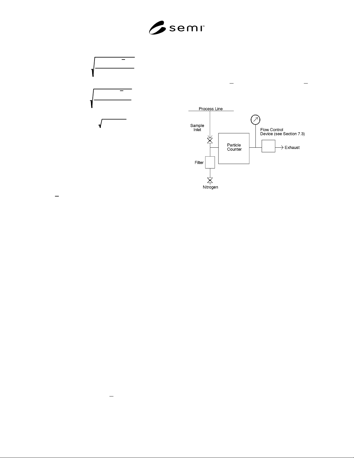
particles in this size range, is shown in Figure 1. Count
a minimum of 3 equal intervals, each of at least 25
standard liters (0.95 SCF), or 30 minutes, whichever is
greater. Calculate
B
X as defined in Section 4.
B
X
must not exceed 2 counts per 25 standard liters.
Figure 1
Schematic Diagram of Configuration for
Obtaining Particle Samples from Inert Specialty
Gas Systems
7.2 The sampling point should be near the point of use,
and sampling lines should be clean and as short as
possible.
7.3 The sampling system configuration is shown in
Figure 1. The specialty gas system should be connected
through a sample valve directly to the particle counter,
a pressure gauge, and a flow control device (FCD).
When sampling is performed using wall tap sample
ports, the aspiration efficiency should be checked using
the method described in Related Information 1. The
sampling system should contain minimum dead volume
and sample tube length. All components in the
sampling system should be leak tight and cleaned in
accordance with good engineering practice. A leak
check of the system should be performed in accordance
with normally accepted practice. The FCD may be part
of the particle counter. The particle counter should be
maintained at the pressure of the gas system. The FCD
can be a metering valve and a flow meter or a critical
orifice. The exhaust line should be leak tight and piped
to an appropriate exhaust system. The exhaust line
diameter should be large enough to produce no more
than 1 × 10
4
Pa (1.5 psi) pressure drop during purge and
sample flow.
NOTE 4: The alternative sampling configurations described
in SEMI C6.5 can also be used for nitrogen or argon.
7.4 Using the high purity nitrogen system shown in
Figure 1, purge the sampling system and particle

SEMI F24-0697 © SEMI 1997, 2003 3
counter for at least 5 minutes at the instrument
manufacturer’s specified flow rate. The exact purge
time should be sufficient to purge the entire exhaust
line. The purging must be performed before sample gas
is introduced into the sampling system and after
completion of the measurement. The valve leading
from the purge nitrogen system should be closed when
sampling specialty gases and/or a back flow prevention
device should be included in the purge nitrogen system.
7.5 Count the particles in each of at least 3 equal
intervals. Each sample interval must be at least 25
standard liters (0.95 SCF), or 30 minutes, whichever is
greater. Data obtained during the first 5 minutes after
the sample valve is opened may be discarded. Record
the number of counts in the sample volume for each
interval. Calculate
C
X and S
C
, as defined in Section 4.
NOTE 5: For small volume specialty gas systems, the user
and supplier may agree to a smaller sample gas volume than
that stated above. The sample point location and the process
line pressure and flow rate during the test should be recorded.
8 Report
8.1 The report shall contain the values of all the
variables defined in Section 4.
9 Related Documents
Hart, J. J., W. T. McDermott, A. E. Holmer, and J. P.
Natwora, Jr. Particle Measurement in Specialty Gases.
Solid State Technol., 38(9):111–116, September 1995.
Wang, H. C. and R. Udischas. Counting Particles in
High Pressure Electronic Specialty Gases. Solid State
Technol., 37(6):97–107, June 1994.
NOTICE: SEMI makes no warranties or
representations as to the suitability of the standards set
forth herein for any particular application. The
determination of the suitability of the standard is solely
the responsibility of the user. Users are cautioned to
refer to manufacturer's instructions, product labels,
product data sheets, and other relevant literature,
respecting any materials or equipment mentioned
herein. These standards are subject to change without
notice.
By publication of this standard, Semiconductor
Equipment and Materials International (SEMI) takes no
position respecting the validity of any patent rights or
copyrights asserted in connection with any items
mentioned in this standard. Users of this standard are
expressly advised that determination of any such patent
rights or copyrights, and the risk of infringement of
such rights are entirely their own responsibility.