semi合集-English.pdf - 第3901页
SEMI F29-0997 © SEMI 1997, 1103 4 9.2.3 Using purified nitr ogen as t he purge gas, complete one purge cycle with the purge gas pressure at 522 kPa (g) [80 psi (g)], vacuum at -75 kPa (g) [-22" Hg (g)], and d well t…
SEMI F29-0997 © SEMI 1997, 1103 3
9.1.5 Record the pressure and peak oxygen concentration in Table 1. It is highly recommended that, in addition to
the peak oxygen concentration, the oxygen concentration readings also be recorded at regular intervals during the
measurement, so that a graph of the oxygen concentration level in the pigtail bleed gas versus time can be drawn if
necessary.
9.1.6 Repeat Sections 9.1.2–9.1.5 for 2, 5, 25, and 50 purge cycles at the manufacturer’s recommended pressure,
vacuum and dwell times. Additional tests using other purge cycle numbers are encouraged and may provide a more
complete characterization of the purge performance of the test piece.
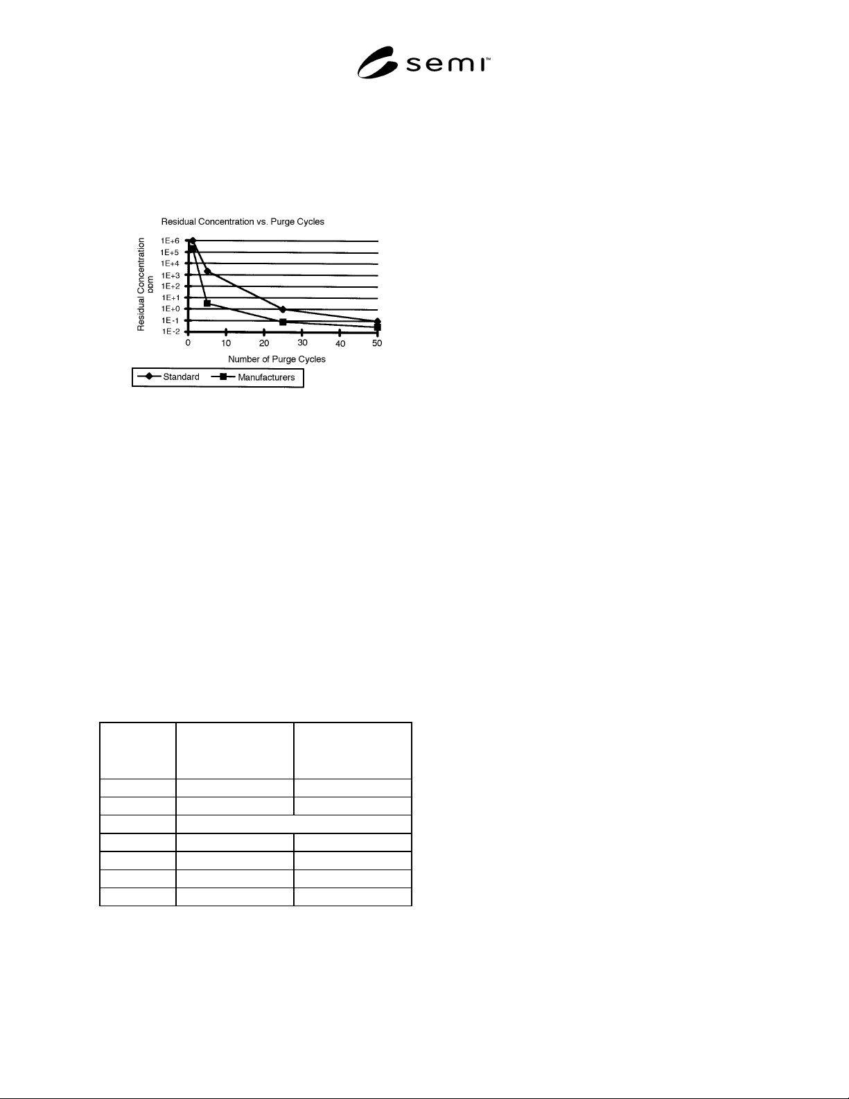
9.1.7 Plot the peak residual oxygen concentration versus cycles as in Figure 2 for manufacturer’s recommended
pressure, vacuum, and dwell times.
9.2 Purge efficacy determination with non-interactive gas at standard pressure, vacuum and dwell times.
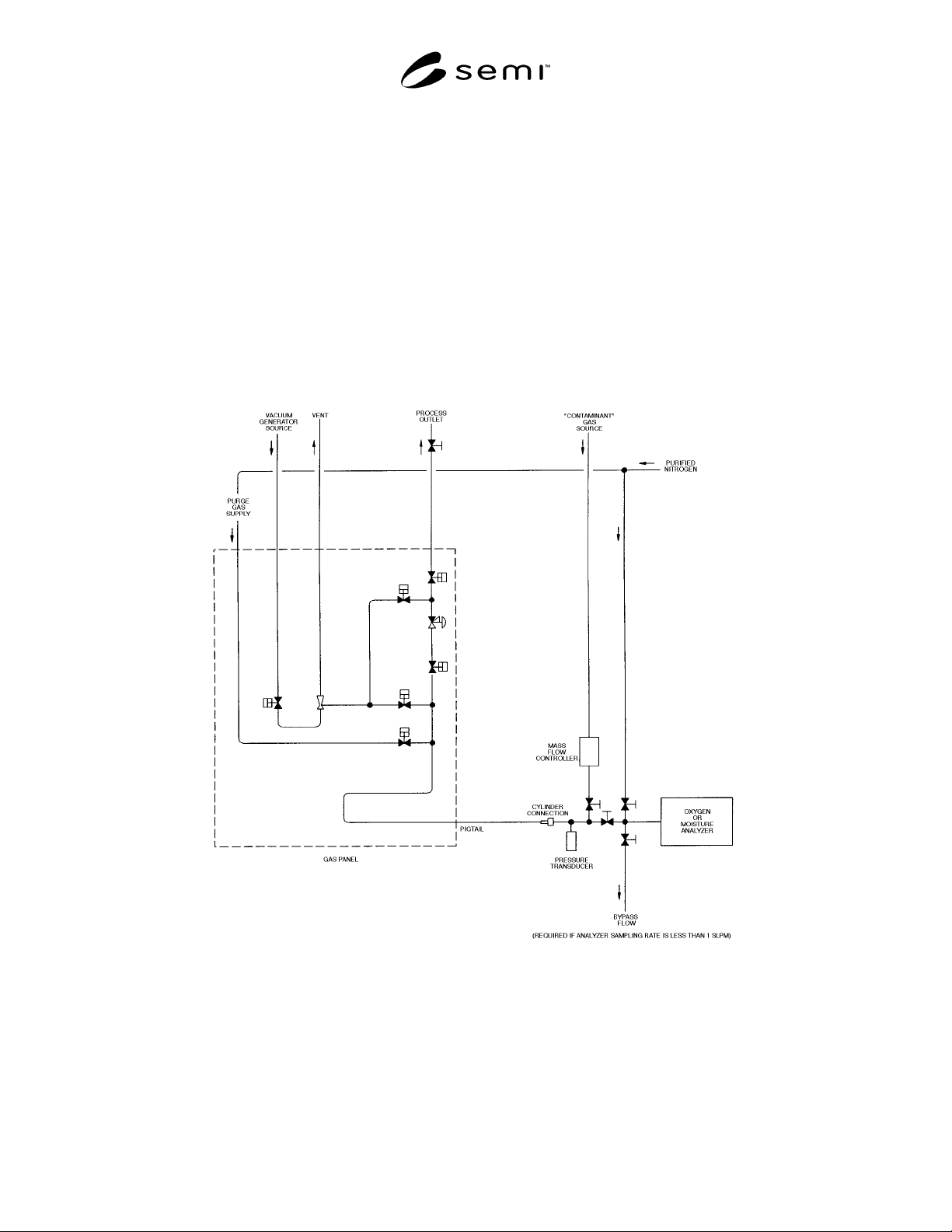
9.2.1 Connect the gas source equipment as in Figure 1.
Figure 1
Test Schematic
9.2.2 To challenge the gas panel with a known contaminant gas, completely fill and pressurize the gas source
system to 207 kPa (g) [30 psi (g)] with CDA as measured at the pigtail with the pressure transducer.
SEMI F29-0997 © SEMI 1997, 1103 4
9.2.3 Using purified nitrogen as the purge gas,
complete one purge cycle with the purge gas pressure at
522 kPa (g) [80 psi (g)], vacuum at -75 kPa (g) [-22"
Hg (g)], and dwell times for pressurization and vacuum
evacuation at 5 and 15 seconds, respectively.
Figure 2
Data Presentation for Purge
Efficacy — Non-Interactive Gas
9.2.4 Flow purified nitrogen using a pigtail bleed at 1
slpm or at the oxygen analyzer manufacturer’s
recommended flow rate, whichever is higher, into the
oxygen analyzer for 10 minutes or until below the
detection limit of the oxygen analyzer.
9.2.5 Record the pressure and vacuum measured with
the transducer and the peak oxygen concentration as in
Table 1. It is highly recommended that, in addition to
the peak oxygen concentration, the oxygen
concentration readings also be recorded at regular
intervals during the measurement, so that a graph of the
oxygen concentration level in the pigtail bleed gas
versus time can be drawn if necessary.
Table 1 Data Collection Form
Manufacturer’s
Recommended Purge
Parameters
SEMI Standard Purge
Parameters
Pressure kPa (g)
Vacuum kPa (g)
Cycles Peak Residual Oxygen
1
5
25
50
9.2.6 Repeat Sections 9.2.2–9.2.5 process for 2, 5, 25,
and 50 cycles. Additional tests using other purge cycle
numbers are encouraged and may provide a more
complete characterization of the purge performance of
the test piece.
9.2.7 Plot the peak residual oxygen concentration
versus number of cycles as in Figure 2 for standard
pressures, vacuum, and dwell time.
9.3 Purge efficacy determination with interactive gas at
manufacturer’s pressure, vacuum, and dwell times.
9.3.1 Connect gas source equipment as in Figure 1.
9.3.2 To challenge the gas panel with a known
contaminant gas, flow wet (2 ppm) N
2
at 2 slpm and
138 kPa (g) [20 psi (g)] for 30 minutes or until the
process outlet concentration reaches the inlet
concentration, whichever is less.
9.3.3 Using purified nitrogen as the purge gas,
complete one purge cycle at manufacturer’s
recommended pressure, vacuum, and dwell times.
9.3.4 Flow purified nitrogen using a pigtail bleed at 1
slpm or at the moisture analyzer manufacturer’s
recommended flow rate, whichever is higher, into the
moisture analyzer for 30 minutes or until below the
detection limit of the moisture analyzer.
9.3.5 Record the pressure and vacuum measured with
the pressure transducer and peak residual moisture
concentration in Table 2. It is highly recommended that,
in addition to the peak moisture concentration, the
moisture concentration readings also be recorded at
regular intervals during the measurement, so that a
graph of the moisture concentration level in the pigtail
bleed gas versus time can be drawn if necessary.
9.3.6 Repeat Sections 9.3.2–9.3.5 process for 2, 3, 4, 5,
10, 25, and 50 cycles. Additional tests using other purge
cycle numbers are encouraged and may provide a more
complete characterization of the purge performance of
the test piece.
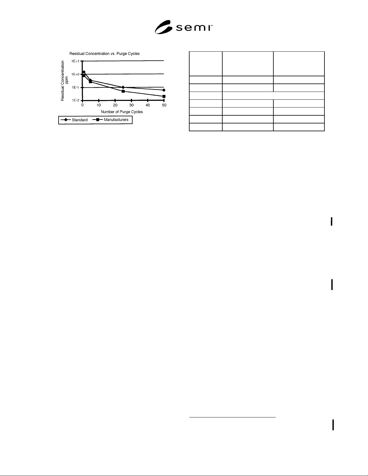
9.3.7 Plot the peak residual moisture concentration
versus number of cycles as in Figure 3 for
manufacturer’s pressure, vacuum, and dwell time.
SEMI F29-0997 © SEMI 1997, 1103 5
Figure 3
Data Presentation for Purge Efficacy
Interactive Gas
9.4 Purge efficacy determination with interactive gas at
standard pressure, vacuum, and dwell time.
9.4.1 Connect gas source equipment as in Figure 1.
9.4.2 To challenge the gas panel with a known
contaminant gas, flow wet (2 ppm) N
2
at 2 slpm and
138 kPa (g) [20 psi (g)] for 30 minutes or until the
process outlet concentration reaches the inlet
concentration, whichever is less.
9.4.3 Using purified nitrogen as the purge gas,
complete one purge cycle with the purge gas pressure at
522 kPa (g) [80 psi (g)], vacuum at -75 kPa (g) [-22"
Hg (g)], and dwell times for pressurization and vacuum
evacuation at 5 and 15 seconds, respectively.
9.4.4 Flow purified nitrogen using a pigtail bleed at 1
slpm or at the moisture analyzer manufacturer’s
recommended flow rate, whichever is higher, into the
moisture analyzer for 30 minutes or until below the
detection limit of the moisture analyzer.
9.4.5 Record the pressure and vacuum measured with
the pressure transducer and peak residual moisture
concentration in Table 2. It is highly recommended that,
in addition to the peak moisture concentration, the
moisture concentration readings also be recorded at
regular intervals during the measurement, so that a
graph of the moisture concentration level in the pigtail
bleed gas versus time can be drawn if necessary.
9.4.6 Repeat Sections 9.4.2–9.4.5 process for 2, 3, 4, 5,
10, 25, and 50 cycles. Additional tests using other purge
cycle numbers are encouraged and may provide a more
complete characterization of the purge performance of
the test piece.
9.4.7 Plot the peak residual moisture concentration
versus number of cycles as in Figure 4 for standard
pressure, vacuum, and dwell time.
Table 2 Data Collection Form
Manufacturer’s
Recommended Purge
Parameters
SEMI Standard Purge
Parameters
Pressure kPa (g)
Vacuum kPa (g)
Cycles Peak Residual Moisture
1
5
25
50
10 Certification
10.1 When specified in the purchase order or contract,
the manufacturer’s or supplier’s certification shall be
furnished to the purchaser stating that the articles
furnished have been tested in accordance with this
specification and the requirements have been met.
When specified in the purchase order or contract, a
report of the test results shall be furnished.
11 Related Documents
11.1 SEMI Standard
SEMI F13 — Guide for Gas Source Control Equipment
11.2 Compressed Gas Association Document
1
CGA Pamphlet P1 — Safe Handling of Compressed
Gases
NOTICE: SEMI makes no warranties or
representations as to the suitability of the standards set
forth herein for any particular application. The
determination of the suitability of the standard is solely
the responsibility of the user. Users are cautioned to
refer to manufacturer’s instructions, product labels,
product data sheets, and other relevant literature
respecting any materials mentioned herein. These
standards are subject to change without notice.
The user’s attention is called to the possibility that
compliance with this standard may require use of
copyrighted material or of an invention covered by
patent rights. By publication of this standard, SEMI
takes no position respecting the validity of any patent
rights or copyrights asserted in connection with any
item mentioned in this standard. Users of this standard
are expressly advised that determination of any such
patent rights or copyrights, and the risk of infringement
of such rights, are entirely their own responsibility.
1 Compressed Gas Association, Inc., 1725 Jefferson Davis Highway,
Suite 1004, Arlington, VA 22202
Copyright by SEMI® (Semiconductor Equipment and Materials
International), 3081 Zanker Road, San Jose, CA 95134. Reproduction o
f
the contents in whole or in part is forbidden without express written
consent of SEMI.