semi合集-English.pdf - 第3988页
SEMI F43-0699 © SEMI 1999 8 Table 1 Parts List for the Recommended Particle Test A pparatus Ite m number Descr iption 1 2 3 4 5 6 7 8 9 10 11 12 13 14 15 16 17 18 19 20 21 22 23 24 25 26 27 28 29 1/4 in. di ameter electr…
SEMI F43-0699 © SEMI 19997
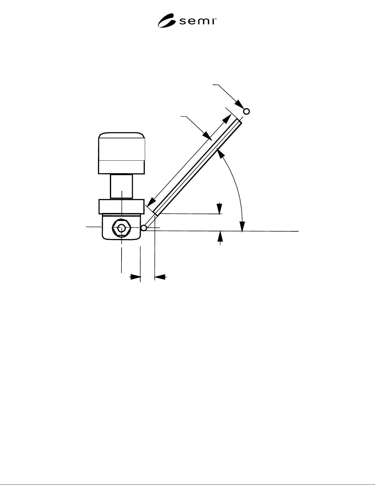
X
1
X
2
X
3
45º
C
L
Suitable
Delivery
Ramp
S.S.
Sphere
Mass = 54.8 ± 1g
X
1
=
30.5 cm ± 0.5
cm
X
2
= 0 cm or very close to it (due to angle and ball size)
X
3
=
2.4 cm ± 0.1 cm
(
dia . of the SS sphere)
TEST
COMPONENT
Figure 2
Mechanical Shock Device
NOTE 1: X3 will change with a change on sphere size.
NOTE 2: Position the delivery ramp so that the position of impact is at the midpoint of the axial centerline of the device under
test.

SEMI F43-0699 © SEMI 1999 8
Table 1 Parts List for the Recommended Particle Test Apparatus
Item
number Description
1
2
3
4
5
6
7
8
9
10
11
12
13
14
15
16
17
18
19
20
21
22
23
24
25
26
27
28
29
1/4 in. diameter electropolished (EP) SS tube
1/4 in. to 1/2 in. tube reducing union
1/2 in. diameter EP SS tube
PTFE membrane filter with 3/8 in. face seal
Pressure regulator, 0-300 inlet pressure, 0-100 outlet pressure
1/2 in. butt weld tee
1/2 in. tube to 3/8 in. NPT female connector
0-60 psig electronics grade pressure gauge
1/2 in. to 1/2 in. union
1/2 in. 3-way SS ball valve
1/4 in. tube to 1/2 in. port reducer
0.2-2 std ft
3
flowmeter
1-15 std ft
3
flowmeter
1/2 in. SS union
1/2 in. dia, 3-ft flexible SS tube
1/2 in. union elbow
1/2 in. pneumatic valve
1/2 in. to 1/4 in. SS reducer gland
Test component
3-way normally closed solenoid air valve
Solenoid valve cycle controller
1/2 in. welded tee
1 1/2 in. dia., 4-ft long exhaust tube
1/2 in. tube to 1/4 in. NPT adapter
1/8 in. dia., 17 in. long SS sample tube
1/4 in. to 1/8 in. reducer union
1/4 in. dia., 30 in. long SS sample loop
1/4 in. to 3/8 in. reducer union
Condensation Nucleus Counter
SEMI F43-0699 © SEMI 19999
APPENDIX 1
SAMPLER DESIGN CRITERIA
A-1.1 The average velocity of gas flo wing through the
sampler should approximate the average velocity in the
tubing in which the sampler is inserted. The sample
flow rate used to calculate the sampler diameter is the
total flow drawn by the counter.
A-1.2 Gradual expansion to atmospheric pressure is
recommended for sampling. Critical orifice expansion
may alter the particle level of the sample.
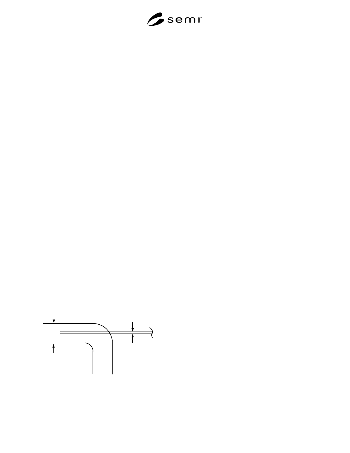
A-1.3 The tip of the sampling probe should have a 30
degree taper on the outside diameter.
A-1.4 The pick-off point should be approximately
centered within the flow stream.
A-1.5 The pick-off point should be approximately 15
diameters of the primary flow tube upstream or
downstream of any connection.
A-1.6 There should be enough volume in the exhaust
portion of the sampler to supply the CNC for one
minute. This volume represents 60 times the volume
that will be drawn by the CNC while the valve is closed
during the dynamic testing. Minimum sample flow
through the CNC is 5 slpm.
A-1.7 State the minimum volume after the probe or
generate a sample blank using the stated volume until
background counts are reached.
Under static flow conditions, the sampler size is within
50% of the size required to achieve isokinetic sampling.
For particles of interest <0.5 um, Hinds
1
and Fissan
2
indicate that any unlikely isokinetic sampling biases are
significant. During dynamic testing, isokinetic
sampling is compromised regardless of the sample tube
size.
D
1
D
2
To
CNC
Isokinetic Sampler Calculation
To establish isokinetic sampling condition:
V
1
= V
2
Q = AV or V = Q/A
so Q
1
/A
1
= Q
2
/A
2
therefore, A
2
= A
1
(Q
2
/Q
1
) or D
2
= D
1
(Q
2
/Q
1
)
1/2
where:
Q = flow rate (volumetric)
A = area (internal cross section)
V = velocity (average)
D = diameter (internal)
subscripts:
1 = main flow line
2 = sample flow line
If pressure correction at point of flow control device is
needed, then:
Q
s
= [(P + 14.7)/14.7]
1/2
x Q
A
where:
Q
A
= actual flow rate
Q
S
= standard flow rate
P = pressure, psig
Temperature variances are assumed to be negligible.
NOTICE: These standards do not purport to address
safety issues, if any, associated with their use. It is the
responsibility of the user of these standards to establish
appropriate safety and health practices and determine
the applicability of regulatory limitations prior to use.
SEMI makes no warranties or representations as to the
suitability of the standards set forth herein for any
particular application. The determination of the
suitability of the standard is solely the responsibility of
the user. Users are cautioned to refer to manufacturer’s
instructions, product labels, product data sheets, and
other relevant literature respecting any materials
mentioned herein. These standards are subject to
change without notice.
The user’s attention is called to the possibility that
compliance with this standard may require use of
copyrighted material or of an invention covered by
patent rights. By publication of this standard, SEMI
takes no position respecting the validity of any patent
rights or copyrights asserted in connection with any
item mentioned in this standard. Users of this standard
are expressly advised that determination of any such
patent rights or copyrights, and the risk of infringement
of such rights, are entirely their own responsibility.
Copyright by SEMI® (Semiconductor Equipment and Materials
International), 3081 Zanker Road, San Jose, CA 95134. Reproduction o
f
the contents in whole or in part is forbidden without express written
consent of SEMI.