semi合集-English.pdf - 第4043页
SEMI F52-1101 © SEMI 200 0, 2001 3 6 Measu rement Pro cedures 6.1 Outside Diameter — Measure the diameters at both ends of t ube wit h a dial th ickness g a uge at 4 points in 45 degree intervals (see Fi gure 1). It is c…
SEMI F52-1101 © SEMI 2000, 2001 2
4.2.5 wall thickness — thickness of the wall of the
PFA tube.
4.2.6 wall thickness deviation — deviation of wall
thickness.
4.2.7 wall thickness tolerance — allowable deviation
of actual measurement of wall thickness from its
specification.
5 Nominal Size and Dimensional Specification
5.1 A nominal tube size is indicated by “outside
diameters/inside diameter”. This document provides
specifications for eight nominal tube sizes as shown in
Table 1.
5.2 The indication of the nominal size for metric PFA
tubes is preferably printed on each package for
shipping.
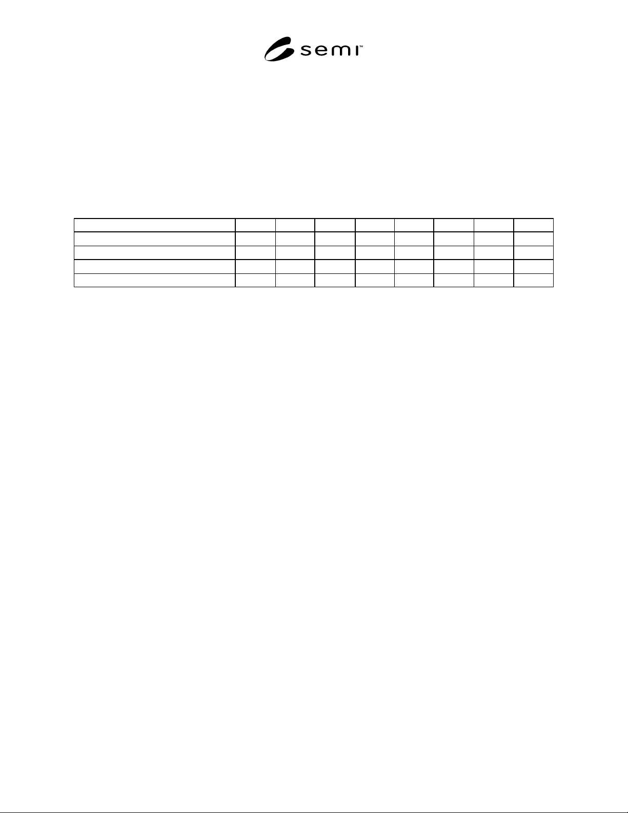
Table 1 Tube Size (mm)
OD/ID 25/22 19/16 12/10 10/8 8/6 6/4 4/3 3/2
OD Tolerance
± 0.2 ± 0.15 ± 0.15 ± 0.12 ± 0.12 ± 0.1 ± 0.1 ± 0.1
Wall Thickness 1.5 1.5 1.0 1.0 1.0 1.0 0.5 0.5
Wall Thickness Tolerance
± 0.15 ± 0.15 ± 0.1 ± 0.1 ± 0.1 ± 0.1 ± 0.05 ± 0.05
Wall Thickness Deviation 0.15 0.15 0.1 0.1 0.1 0.1 0.05 0.05
NOTE 1: The specified sizes should be measured at 23 ± 3°C. The specimen should be kept in the environment for more than 1 hour prior to the
measurement.
NOTE 2: Refer to JASO F 409-91 and JASO M 317-73 for outside and inside diameter of 10/8, 8/6 and 6/4 tubes.
NOTE 3: Refer to JIS B 8183 for outside and inside diameter of 8/6 and 6/4 tubes.
NOTE 4: Refer to JIS B 6890 for outside and inside diameter of 12/10, 10/8, 8/6, 6/4, 4/3 and 3/2 tubes.
NOTE 5: Refer to SAE J 844 for outside diameter of 19/16 tube.
NOTE 6: Refer to SAE J 1394 for outside and inside diameter of 8/6 and 6/4 tubes.
NOTE 7: Refer to ISO 4397 for outside diameter of 25/22, 12/10, 10/8, 8/6 and 4/3 tubes.
SEMI F52-1101 © SEMI 2000, 20013
6 Measurement Procedures
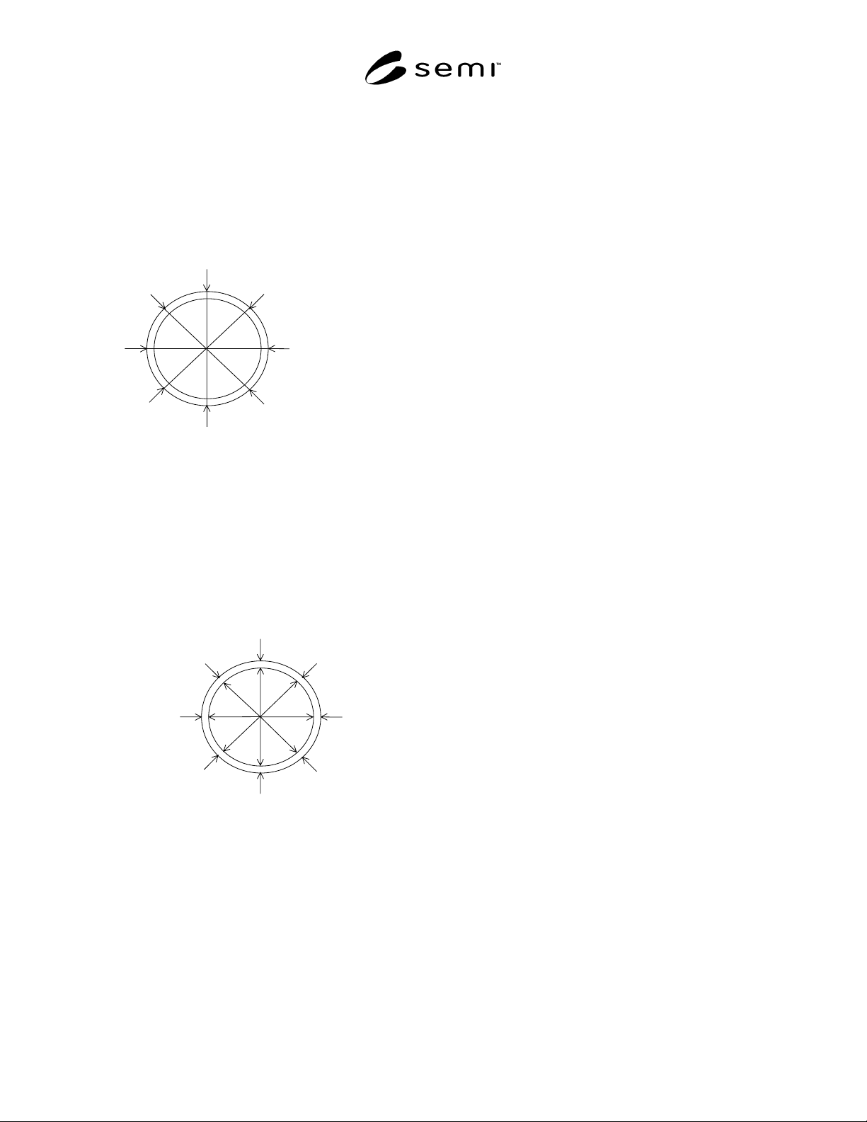
6.1 Outside Diameter — Measure the diameters at both
ends of tube with a dial thickness gauge at 4 points in
45 degree intervals (see Figure 1). It is calculated with
the following formula:
Outside Diameter = 1/2 * (maximum reading +
minimum reading)
Measuring Point No.1
Measuring Point No.2
Measuring Point No.3
Measuring Point No.4
Figure 1
Outside Diameter Measurement
6.2 Wall Thickness — Measure the wall thickness at
both ends of tube with a dial thickness gauge at 8 points
in 45 degree intervals (see Figure 2). If it is not
practical to use a dial thickness gauge, prepare a 1 mm
long test piece and measure it with a projector. It is
calculated with the
following formula:
Wall Thickness = 1/2 * (maximum reading + minimum
reading)
Measuring Point No.1
Measuring
Point No.2
Measuring
Point No.3
Measuring
Point No.4
Measuring Point No.5
Measuring
Point No.6
Measuring
Point No.7
Measuring
Point No.8
Figure 2
Wall Thickness Measurement
6.3 Wall Thickness Deviation — Use maximum and
minimum readings of Section 6.2 and calculate the
deviation with the following formula:
Wall Thickness Deviation = maximum reading –
minimum reading
6.4 Other specifications including surface roughness,
deviation from circular form, and physical property
values may be determined upon agreement between the
supplier and user.
6.5 Refer to JIS B 7502, External Micrometer for a dial
thickness gauge.
7 Related Documents
7.1 SEMI Standards
SEMI F7 — Test Method to Determine the Tensile
Strength of Tube Fitting Connections Made of
Fluorocarbon Materials
SEMI F8 — Test Method for Evaluating the Sealing
Capabilities of Tube Fitting Connections Made of
Fluorocarbon Materials, When Subjected to Tensile
Forces
SEMI F9 — Test Method to Determine the Leakage
Characteristics of Tube Fitting Connections Made of
Fluorocarbon Materials, When Subjected to a Side
Load Condition
SEMI F10 — Test Method to Determine the Internal
Pressure Required to Produce a Failure of a Tube
Fitting Connection Made of Fluorocarbon Materials
SEMI F11 — Test Method to Obtain an Indication of
the Thermal Characteristics of Tube Fitting
Connections Made of Fluorocarbon Materials
SEMI F12 — Test Method to Determine the Sealing
Capabilities of Fittings, Made of Fluorocarbon
Materials, after Being Subjected to a Heat Cycle
NOTICE: SEMI makes no warranties or
representations as to the suitability of the specification
set forth herein for any particular application. The
determination of the suitability of the specification is
solely the responsibility of the user. Users are
cautioned to refer to manufacturer’s instructions,
product labels, product data sheets, and other relevant
literature respecting any materials mentioned herein.
These specifications are subject to change without
notice.
The user’s attention is called to the possibility that
compliance with this specification may require use of
copyrighted material or of an invention covered by
patent rights. By publication of this specification,
SEMI takes no position respecting the validity of any
patent rights or copyrights asserted in connection with
any item mentioned in this specification. Users of this
specification are expressly advised that determination
of any such patent rights or copyrights, and the risk of
infringement of such rights, are entirely their own
responsibility.
Copyright by SEMI® (Semiconductor Equipment and Materials
International), 3081 Zanker Road, San Jose, CA 95134. Reproduction o
f
the contents in whole or in part is forbidden without express written
consent of SEMI.

SEMI F53-0600 © SEMI 20001
SEMI F53-0600
TEST METHOD FOR EVALUATING THE ELECTROMAGNETIC
SUSCEPTIBILITY OF THERMAL MASS FLOW CONTROLLERS
This test method was technically approved by the Global Facilities Committee and is the direct responsibility
of the North American Facilities Committee. Current edition approved by the North American Regional
Standards Committee on March 2, 2000. Initially available on www.semi.org April 2000; to be published
June 2000.
1 Purpose
1.1 The purpose of this document is to define a
structured method for testing and evaluating the
electromagnetic susceptibility of thermal mass flow
controllers.
2 Scope
2.1 This document contains the requirements and test
method that can be used to evaluate whether a thermal
mass flow controller will maintain its functional
characteristics when subjected to EMI levels typical of
the industry. The test method covers both the radiated
susceptibility (RS) and conducted susceptibility (CS) of
the controller when exposed to EMI. The
electromagnetic susceptibility requirements are
extracted from MIL-STD-461C and SAMA PMC-33.1,
and the test method is a composite of the RS03, CS01,
CS02, and CS06 test methods defined in MIL-STD 462.
2.2 This test method does not purport to address safety
issues, if any, associated with its use. It is the responsi-
bility of the users of this test method to establish
appropriate safety and health practices and determine
the applicability of regulatory limitations prior to use.
3 Limitations
3.1 This test method is not designed for AC-powered
MFCs. The test method addresses electromagnetic
susceptibility of MFCs through DC power leads and
control signals.
4 Referenced Standards
4.1 Military Standards
1
MIL-STD-461C Electromagnetic Emission and
Susceptibility Requirements for the Control of
Electromagnetic Interference
MIL-STD-462 Measurement of Electromagnetic
Interference Characteristics
1 Available from Naval Publications and Forms Center, 5801 Tabor
Ave., Philadelphia, PA 19120
MIL-STD-463A Electromagnetic Interference and
Electromagnetic Compatibility Technology Definitions
and Systems of Units
4.2 Scientific Apparatus Makers Associations
2
SAMA PMC 33.1 Electromagnetic Susceptibility of
Process Control Instrumentation, Scientific Apparatus
Makers Associations
NOTE 1: As listed or revised, all documents cited shall be the
latest publications of adopted standards.
5 Terminology
5.1 Abbreviations and Acronyms
5.1.1 CS — conducted susceptibility
5.1.2 dB — decibels
5.1.3 DC — direct current
5.1.4 EMC — electromagnetic compatibility
5.1.5 EMI — electromagnetic interference
5.1.6 GHz — gigahertz
5.1.7 kHz — kilohertz
5.1.8 MFC — mass flow controller
5.1.9 MHz — megahertz
5.1.10 MIL-STD — Military Standard
5.1.11 psia — pounds per square inch absolute
5.1.12 psig — pounds per square inch gauge
5.1.13 RF — radio frequency
5.1.14 RG-58 — a specification for a particular type of
coaxial cable
5.1.15 rms — root mean square
5.1.16 RS — radiated susceptibility
5.1.17 T — teslas
2 Portions of this method are excerpted from SAMA Standard PMC
31.1-1980 with permission of the publisher, Process Measurements &
Control Section, SAMA, 1101 16th St., N. W. Washington, DC
20036