semi合集-English.pdf - 第4115页
SEMI F60-0301 © SEMI 2001 11 NOTICE: SEMI makes no warr antie s or representations as to the suitabilit y of the standards set forth herein for any particular application. The determination of the suitability o f the sta…
SEMI F60-0301 © SEMI 2001 10
Theoretical
0
10
20
30
40
50
60
70
80
90
100
0 5 10 15 20 25 30 35 40 45
Angstroms
Atomic Concentration
Cr Fe Ni Mo O C
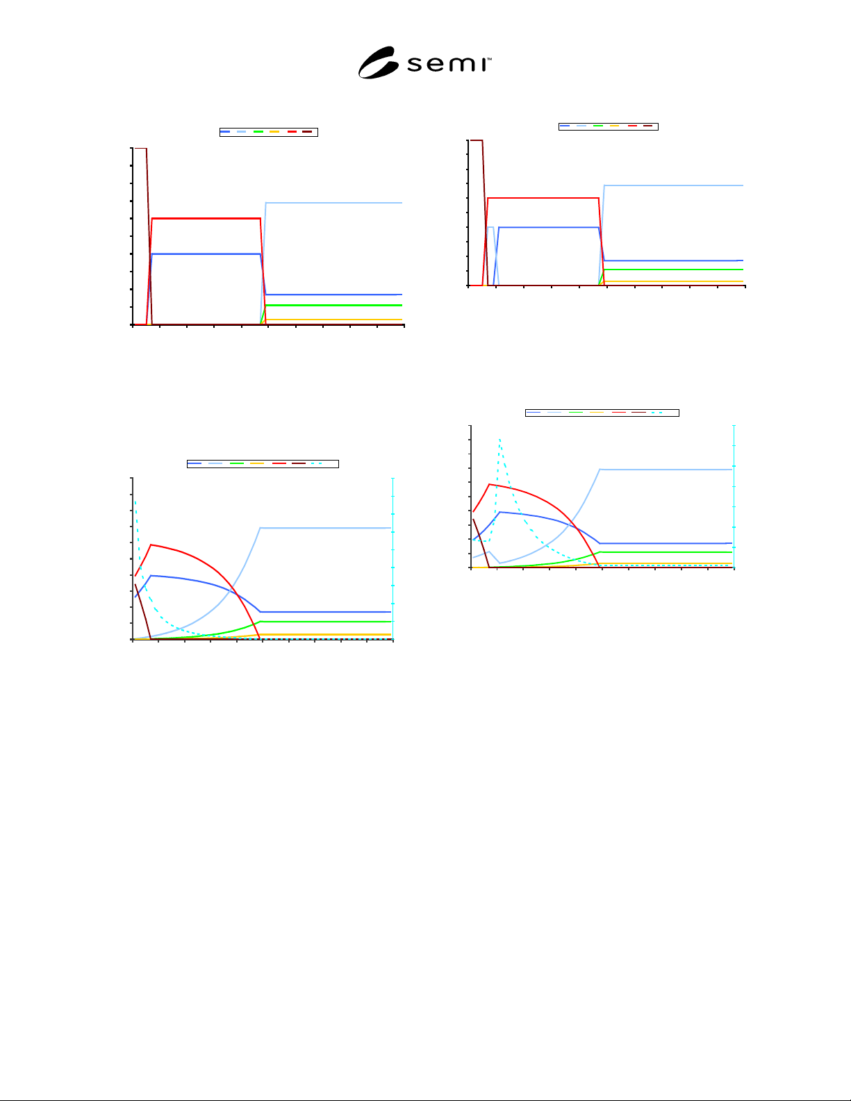
Figure A1-9
Composition versus depth of a carbon layer over a
Cr
2
O
3
layer on stainless steel.
Convoluted 5 Lambda
0
10
20
30
40
50
60
70
80
90
100
0 5 10 15 20 25 30 35 40 45
Angstroms
Atomic Concentration
0
10
20
30
40
50
60
70
80
90
Cr Fe Ni Mo O C Cr:Fe
Figure A1-10
Theoretical depth profile of Figure A1-9 assuming
5λ
λλ
λ depth of analysis.
A1-1.11 The model composition profile of Figure A1-
11 shows a 3 angstrom carbon layer over 3 Å of pure
Fe
2
O
3
over 19 Å of pure Cr
2
O
3
on 316L stainless steel.
Figure A1-12 is the theoretical depth profile of this
model assuming a depth of analysis of 5λ. This profile
is seen to be similar to the depth profiles generally
observed for passivated stainless steel. The Cr:Fe ratio
maximum occurs below the initial surface, and the
initial surface atomic concentrations of the elements of
interest are diluted by the presence of the carbon layer
on the surface. The oxide thickness, as measured by the
FWHM technique, is affected by both the presence of
the carbon layer and the depth of analysis.
Theoretical
0
10
20
30
40
50
60
70
80
90
100
0 5 10 15 20 25 30 35 40 45
Angstroms
Atomic Concentration
Cr Fe Ni Mo O C
Figure A1-11
Composition versus depth of a carbon layer over a
Fe
2
O
3
layer over a Cr
2
O
3
layer on stainless steel.
Convoluted 5 Lambda
0
10
20
30
40
50
60
70
80
90
100
0 5 10 15 20 25 30 35 40 45
Angstroms
Atomic Concentration
0
2
4
6
8
10
12
14
Cr Fe Ni Mo O C Cr:Fe
Figure A1-12
Theoretical depth profile of Figure A1-11 assuming
5λ
λλ
λ depth of analysis.
A1-1.12 It must be emphasized that these derived
depth profiles are for models with perfect interfaces and
perfect compositions instead of the compositional
gradients observed in real systems. Additional
measurement uncertainties result from roughness and
non-planarity of the surface, and from differential
sputtering rates for different chemical species during
depth profiling.
A1-1.13 The depth profiles of real systems must be
interpreted with an understanding of the effects
described in this Appendix and a realization that they
are not ideal. The same considerations pertain to Auger
depth profile analysis.

SEMI F60-0301 © SEMI 200111
NOTICE: SEMI makes no warranties or
representations as to the suitability of the standards set
forth herein for any particular application. The
determination of the suitability of the standard is solely
the responsibility of the user. Users are cautioned to
refer to manufacturer’s instructions, product labels,
product data sheets, and other relevant literature
respecting any materials mentioned herein. These
standards are subject to change without notice.
The user’s attention is called to the possibility that
compliance with this standard may require use of
copyrighted material or of an invention covered by
patent rights. By publication of this standard, SEMI
takes no position respecting the validity of any patent
rights or copyrights asserted in connection with any
item mentioned in this standard. Users of this standard
are expressly advised that determination of any such
patent rights or copyrights, and the risk of infringement
of such rights, are entirely their own responsibility.
Copyright by SEMI® (Semiconductor Equipment and Materials
International), 3081 Zanker Road, San Jose, CA 95134. Reproduction o
f
the contents in whole or in part is forbidden without express written
consent of SEMI.

SEMI F61-0301 © SEMI 20011
SEMI F61-0301
GUIDE FOR ULTRAPURE WATER SYSTEM USED IN
SEMICONDUCTOR PROCESSING
This guide was technically approved by the Global Facilities Committee and is the direct responsibility of the
North American Facilities Committee. Current edition approved by the North American Regional Standards
Committee on November 22, 2000. Initially available at www.semi.org December 2000; to be published
March 2001.
1 Purpose
1.1 This guide establishes the typical definitional
requirements for an ultrapure water (UPW) system used
in semiconductor manufacturing. It is intended to
establish a common basis for developing detailed
specifications in subsequent documents concerning
design, performance and certification and monitoring of
UPW systems.
1.2 This document may be used by users and suppliers
as a basis for developing site-specific UPW
specifications and performance criteria.
2 Scope
2.1 This guide applies to ultrapure water systems used
in semiconductor manufacturing facilities for supplying
high purity water for chemical dilutions, wafer
processing and other manufacturing processes.
2.2 This guide can be used to understand the design
elements and functionality of all UPW systems, which
includes a Reverse Osmosis (RO) and a Deionization
(DI) process. However, it is most applicable to newer
designed UPW systems that support submicron
linewidth device manufacturing.
2.3 This standard does not purport to address safety
issues, if any, associated with its use. It is the
responsibility of the users of this standard to establish
appropriate safety and health practices and determine
the applicability of regulatory limitations prior to use.
3 Limitations
3.1 This guide does not define the actual specifications
generally negotiated between the user and the
manufacturer of the UPW system, against which water
samples are tested and qualification is passed.
3.2 This guide does not address the testing and
prequalification of materials, subassemblies, or
components used in a UPW system.
3.3 This guide does not address the protocols and
requirements defined by the manufacturer concerning
the installation of the UPW system.
3.4 This guide does not address the type, level, or
frequency of testing necessary and appropriate for
ongoing monitoring of a UPW system.
3.5 This guide does not address the frequency or scope
of ongoing maintenance for UPW systems including
change out of resin beds and replacement of filters.
3.6 This guide does not intend to cover any of the
important safety considerations that relate to the proper
installation, operation, or maintenance of a UPW
system.
4 Terminology
4.1 Acronyms and Abbreviations
4.1.1 TOC Total organic carbon, also Total
Oxidizable Carbon. Refers to organic compounds.
4.1.2 UPW — Ultrapure Water System consisting of
multiple components including a Reverse Osmosis
(RO) and a Deionization (DI) process.
4.2 Definitions
4.2.1 activated Carbon a media filter used to
remove oxidizing agents, like chlorine and chloramines,
and remove (adsorb) certain TOC compounds.
4.2.2 anion a negatively charged ion.
4.2.3 cation a positively charged ion.
4.2.4 clarifier a piece of water treatment
equipment, typically used at municipal drinking water
plants, to remove suspended solids from surface water
and/or to soften surface water.
4.2.5 degasification the removal of a certain
amount of volatile compounds dissolved in water.
4.2.6 deionization (DI) the removal of undesirable
ions from water.
4.2.7 DI storage generally refers to a storage tank
that contains DI water, located between the primary and
polishing ion exchange subsystems.
4.2.8 DI (deionized) water generally refers to water
that has passed through a full-train ion exchange system
or RO water that has been polished by ion exchange.