semi合集-English.pdf - 第4175页
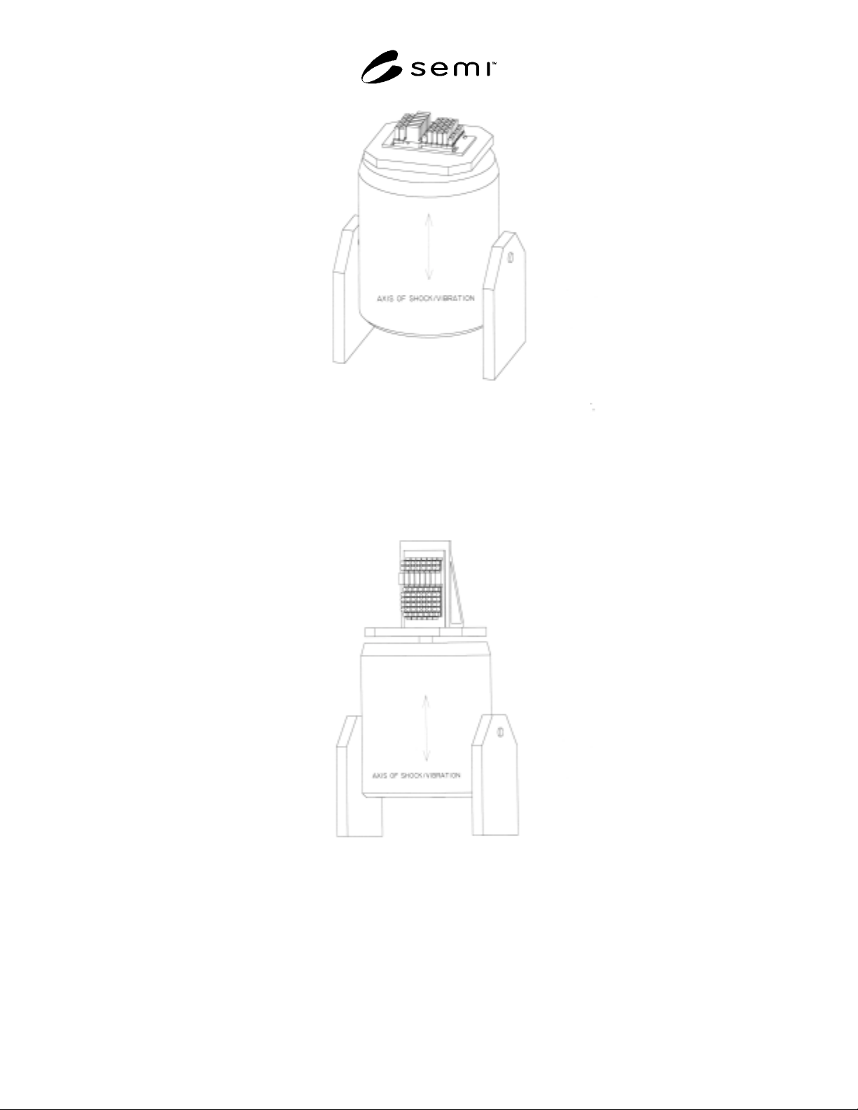
SEMI F69-0302 © SEMI 2002 3 NOTE 1: Plane of g as stic ks is pa rallel to shock/v ibe table and transv erse to test input. Figure 1 Horizonta l Orientation NOT E 1: Plane and ax es of gas sticks are nor mal to shock /vib…

SEMI F69-0302 © SEMI 2002 2
systems to the equivalent physical stress of a 4828
kilometer (3000 mile) motor freight shipment over
improved or paved highways. Because vibration tables
are commonly single-axis devices, the gas delivery
systems will be subjected to single-axis random
vibrational frequencies in the range of 5—500 Hz,
sequentially, in each of its three axes.
6.2 Prior to initiating the test, examine the gas delivery
systems for physical defects and document the results.
6.3 Prior to initiating the test, thoroughly prepare the
gas delivery systems for testing. This includes, but is
not limited to, insuring all fasteners and sealing
mechanisms are tightened to manufacturers’ or design
specifications.
6.4 The MIL-STD-810 transportation test
recommended herein provides for different acceleration
levels for each of the 3 axes of the device under test.
Because the majority of gas delivery systems are
shipped in a vertical orientation, this convention is
maintained for the purpose of the transportation
simulation tests. Thus the vertical orientation would
have the gas delivery system mounted vertically with
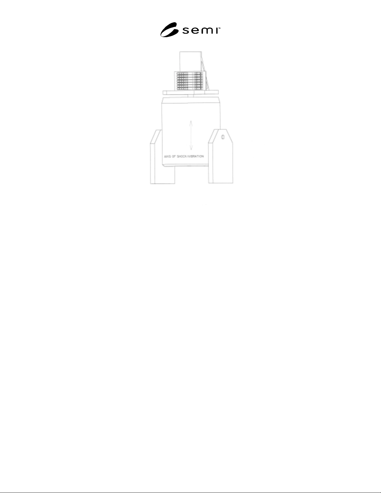
respect to the vibration table top (see Figure 2), the
longitudinal orientation would have the gas delivery
system mounted flat to the vibration table top (see
Figure 1), and the transverse orientation would have the
gas delivery system mounted on its side, against the
vibration table top (see Figure 3). Note that the terms
“vertical,” “longitudinal,” and “transverse,” are
contextual to motor freight transport, and receive
different acceleration levels, within MIL-STD-810. A
simplified and conservative approach to applying MIL-
STD-810 involves applying the highest acceleration
level, associated with the vertical axis, to all three
orientations as illustrated in Figures 1–3.
6.5 Mount the gas delivery system, in any of its
untested axes, securely to the vibration table. See
Figures 1–3.
6.6 Prior to initiating the test at the test site, make
certain that the gas delivery system is leak tight using
inboard test procedures per SEMI F1. A bag leak test
method is recommended in conjunction with this test.
6.7 Initiate and run for 3 hours the vibration test
corresponding to the orientation of the gas delivery
system.
6.8 At the conclusion of the test, examine the gas panel
for physical defects and document the results
6.9 At the conclusion of the test, leak test the gas
delivery system using inboard leak procedures per
SEMI F1. A bag leak test method is recommended in
conjunction with this test. Alternatively, by agreement
with the customer, all leak testing may be withheld until
completion of all shock and vibration testing. This
presumes specific failure mode information is not
required.
6.10 Repeat Sections 6.5 through 6.9 until all 3 axes
are tested.
6.11 The post-test report should include, at minimum,
the following:
(1) Pre-test examination results.
(2) Pre-test leak rates.
(3) Summary and chronology of test events, test
interruptions, and test failures.
(4) All vibration measurement data.
(5) Post-test examination results.
(6) Post-test leak rates.
SEMI F69-0302 © SEMI 2002 3
NOTE 1: Plane of gas sticks is parallel to shock/vibe table and transverse to test input.
Figure 1
Horizontal Orientation
NOTE 1: Plane and axes of gas sticks are normal to shock/vibe table and parrallel to test input.
Figure 2
Vertical Orientation
SEMI F69-0302 © SEMI 2002 4
NOTE 1: Plane of gas sticks is normal to shock/vibe table and axes of sticks are transverse to test input.
Figure 3
Lateral Orientation
7 Shock Testing
7.1 In general, conduct shock testing according to
MIL-STD-810, Part Two, Laboratory Test Method
516.5, Procedure 1 (Functional Shock). This test will
subject the gas delivery system to a peak acceleration of
40 g’s employing a terminal peak sawtooth shock pulse.
7.2 The test should be conducted in each of the gas
delivery system’s three axes as illustrated in Figures 1–
3.
7.3 Prior to initiating the test, examine the gas delivery
system for physical defects and document the results.
7.4 Prior to initiating the test, thoroughly prepare the
gas delivery system for testing. This includes, but is
not limited to, insuring all fasteners and sealing
mechanisms are tightened to manufacturers’ or design
specifications.
7.5 Prior to initiating the test, make certain that the gas
delivery system is leak tight using inboard test
procedures per SEMI F1. A bag leak test method is
recommended in conjunction with this test.
7.6 Secure the gas delivery system under test to the
shock table in one of its three orientations: horizontal,
vertical, or lateral. The gas delivery system should be
fastened directly to the table with no cushion or other
intermediary between the two. A rigid mounting is
desirable, taking caution not to introduce stress to the
gas delivery system.
7.7 Conduct the shock test.
7.8 At the conclusion of the test, examine the gas panel
for physical defects and document the results.
7.9 If, as a result of the test, an apparent physical
failure occurred that would likely prevent the safe
operation of the gas panel and/or would likely
compromise the leak tightness of the gas panel, the
physical failure should be corrected, the gas panel
retested for leak tightness, and the test repeated.
7.10 At the conclusion of the test, leak test the gas
delivery system using inboard leak procedures per
SEMI F1. A bag leak test method is recommended in
conjunction with this test. Alternatively, by agreement
with the customer, all leak testing may be withheld until
completion of all shock and vibration testing. This
presumes specific failure mode information is not
required.
7.11 Repeat 7.6 through 7.10 for a second orientation.
7.12 Repeat 7.6 through 7.10 for the third and final
orientation.