semi合集-English.pdf - 第4176页
SEMI F69-0302 © SEMI 2002 4 NOTE 1: Plane of gas stick s is normal to sh ock/vibe table and axes of sticks are transvers e to test input. Figure 3 Lateral Orienta tion 7 Shock T esting 7.1 In general, conduct shock testi…
SEMI F69-0302 © SEMI 2002 3
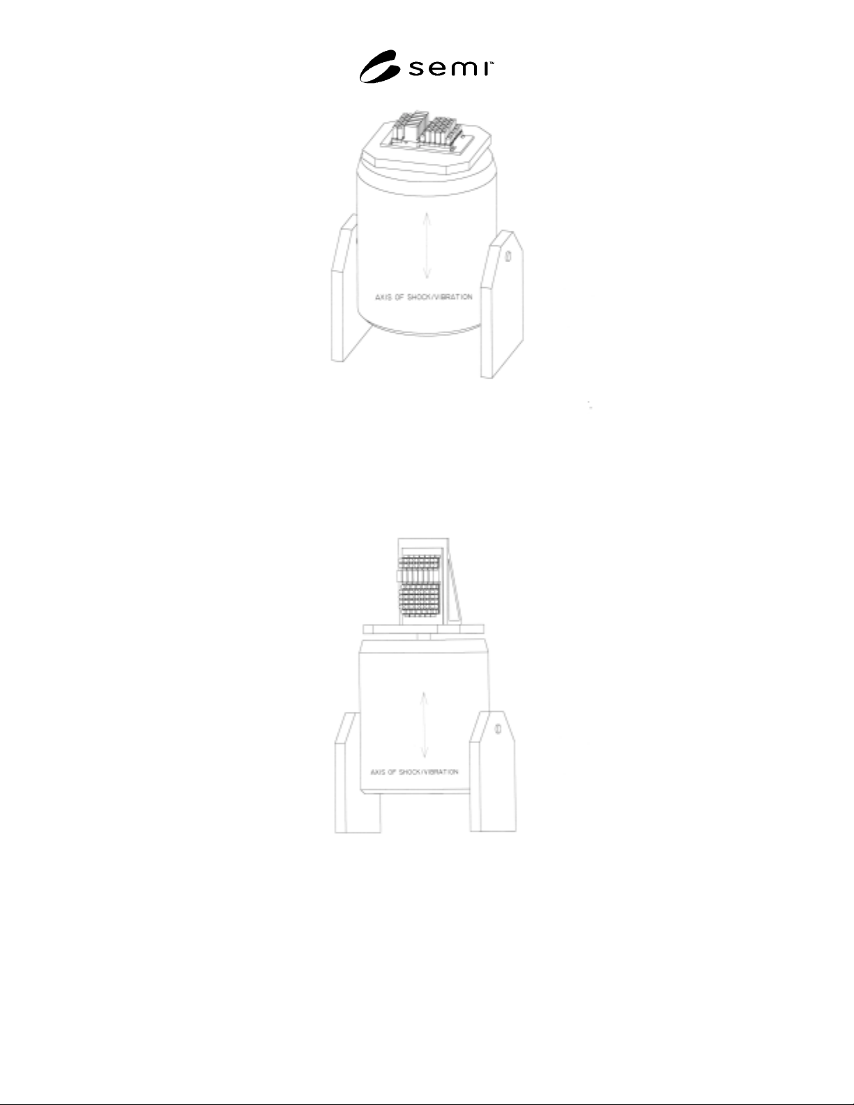
NOTE 1: Plane of gas sticks is parallel to shock/vibe table and transverse to test input.
Figure 1
Horizontal Orientation
NOTE 1: Plane and axes of gas sticks are normal to shock/vibe table and parrallel to test input.
Figure 2
Vertical Orientation
SEMI F69-0302 © SEMI 2002 4
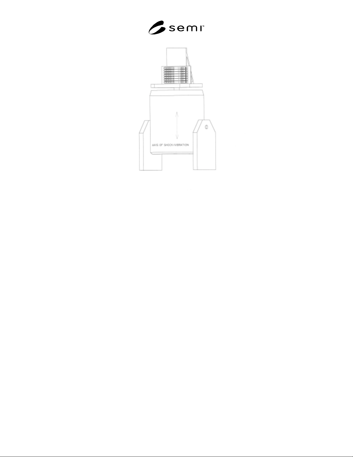
NOTE 1: Plane of gas sticks is normal to shock/vibe table and axes of sticks are transverse to test input.
Figure 3
Lateral Orientation
7 Shock Testing
7.1 In general, conduct shock testing according to
MIL-STD-810, Part Two, Laboratory Test Method
516.5, Procedure 1 (Functional Shock). This test will
subject the gas delivery system to a peak acceleration of
40 g’s employing a terminal peak sawtooth shock pulse.
7.2 The test should be conducted in each of the gas
delivery system’s three axes as illustrated in Figures 1–
3.
7.3 Prior to initiating the test, examine the gas delivery
system for physical defects and document the results.
7.4 Prior to initiating the test, thoroughly prepare the
gas delivery system for testing. This includes, but is
not limited to, insuring all fasteners and sealing
mechanisms are tightened to manufacturers’ or design
specifications.
7.5 Prior to initiating the test, make certain that the gas
delivery system is leak tight using inboard test
procedures per SEMI F1. A bag leak test method is
recommended in conjunction with this test.
7.6 Secure the gas delivery system under test to the
shock table in one of its three orientations: horizontal,
vertical, or lateral. The gas delivery system should be
fastened directly to the table with no cushion or other
intermediary between the two. A rigid mounting is
desirable, taking caution not to introduce stress to the
gas delivery system.
7.7 Conduct the shock test.
7.8 At the conclusion of the test, examine the gas panel
for physical defects and document the results.
7.9 If, as a result of the test, an apparent physical
failure occurred that would likely prevent the safe
operation of the gas panel and/or would likely
compromise the leak tightness of the gas panel, the
physical failure should be corrected, the gas panel
retested for leak tightness, and the test repeated.
7.10 At the conclusion of the test, leak test the gas
delivery system using inboard leak procedures per
SEMI F1. A bag leak test method is recommended in
conjunction with this test. Alternatively, by agreement
with the customer, all leak testing may be withheld until
completion of all shock and vibration testing. This
presumes specific failure mode information is not
required.
7.11 Repeat 7.6 through 7.10 for a second orientation.
7.12 Repeat 7.6 through 7.10 for the third and final
orientation.

SEMI F69-0302 © SEMI 2002 5
7.13 The post-test report should include, at minimum,
the following:
1) Pre-test examination results.
2) Pre-test leak rate.
3) Summary and chronology of test events, test
interruptions, and test failures.
4) All shock measurement data, including that of any
accelerometers mounted to the gas delivery system.
5) Post-test examination results for all three axes.
6) Post-test leak rate for all three shock tests.
NOTICE: SEMI makes no warranties or
representations as to the suitability of the standards set
forth herein for any particular application. The
determination of the suitability of the standard is solely
the responsibility of the user. Users are cautioned to
refer to manufacturer’s instructions, product labels,
product data sheets, and other relevant literature
respecting any materials mentioned herein. These
standards are subject to change without notice.
The user’s attention is called to the possibility that
compliance with this standard may require use of
copyrighted material or of an invention covered by
patent rights. By publication of this standard, SEMI
takes no position respecting the validity of any patent
rights or copyrights asserted in connection with any
item mentioned in this standard. Users of this standard
are expressly advised that determination of any such
patent rights or copyrights, and the risk of infringement
of such rights, are entirely their own responsibility.
Copyright by SEMI® (Semiconductor Equipment and Materials
International), 3081 Zanker Road, San Jose, CA 95134 Reproduction o
f
the contents in whole or in part is forbidden, without express writte
n
content of SEMI.