semi合集-English.pdf - 第4183页
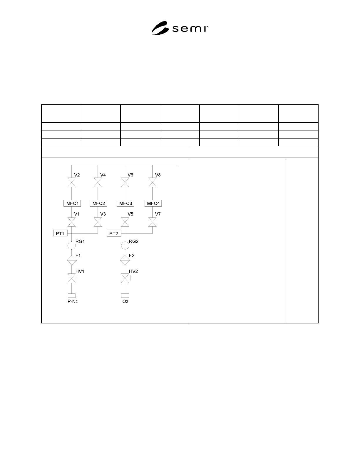
SEMI F70-0302 © SEMI 2002 6 A PPENDIX 1 SA M PLE REPORT FORM A T FOR STA TI C FLOW PA RTICLE TEST NOTE: This appendix is being balloted as an official pa rt of SEMI F70 by f ull letter ballo t procedures, but the recomm …

SEMI F70-0302 © SEMI 2002
5
9.4.5 Repeat Sections 9.4.1 to 9.4.4 per all lines.
NOTE 2: For the pulse test, the total volume of the test flow
shall be half of the test flow rate multiplied by the sampling
time.
10 Calculation and Report
10.1 The following test conditions are to be included in
the test report:
• counter type (LPC or CNC)
• manufacturer of counter
• counter model (manufacturer’s model # or part #)
• sample flow
• particle diameter
• sampler diameter
• sample probe diameter
• test gas
• background count
• valve operation interval (for the pulse flow test)
• flow diagram of the system under test
10.2 Calculation of Data — The test result is reported
in number of particles in liters denoted by floating point
representation with two significant digits (ex. 2.3 × 10
-
2
/L). The method of calculation is shown in Section
10.2.1.
10.2.1 The following formula is used to calculate the
particles in a liter:
PARTICLES
N
V
=
where N: Total particle counts in 10 minutes or in the
extended period if the total volume of the test flow is
less than 28.3 liters.
V: Total sampling volume in liter in 10 minutes (mass
flow meter read value) or in the extended period if the
total volume of the test flow is less than 28.3 liters.
If the sample flow rate is equal to or more than the test
flow rate, V is equal to the total volume of the test flow
in liter in the sampling time.
If the sample flow rate is less than the test flow rate, V
is equal to the total volume of the sample flow in liter in
the sampling time.
10.3 Report Format — Sample report formats are
given in Appendixes 1 and 2.
SEMI F70-0302 © SEMI 2002
6
APPENDIX 1
SAMPLE REPORT FORMAT FOR STATIC FLOW PARTICLE TEST
NOTE: This appendix is being balloted as an official part of SEMI F70 by full letter ballot procedures, but the
recommendation in this appendix are optional and are not required to conform to this standard.
STATIC FLOW PARTICLE TEST REPORT
Line Design Flow
(l/min)
Test Flow (l/min) Sampling Method Total sampling
volume (l)
Total particle
count
Particle Count
(particle/l)
P-N
2
200 300 Partial Sampling 283 3
1.1 × 10
-2
O
2
10 15 Full Sampling 150 2
1.3 × 10
-2
Flow Diagram of System Under Test Test Condition
Counter Type:
Manufacturer of the Counter
Counter Model
Sample Flow:
Particle Diameter:
Sampler Diameter:
Sample Probe Diameter:
Test Gas
Background Count:
LPC
A
B
28.3 l/min
≥ 0.1 µ m
30.0 mm
7.53 mm
LN
2
0
SEMI F70-0302 © SEMI 2002
7
APPENDIX 2
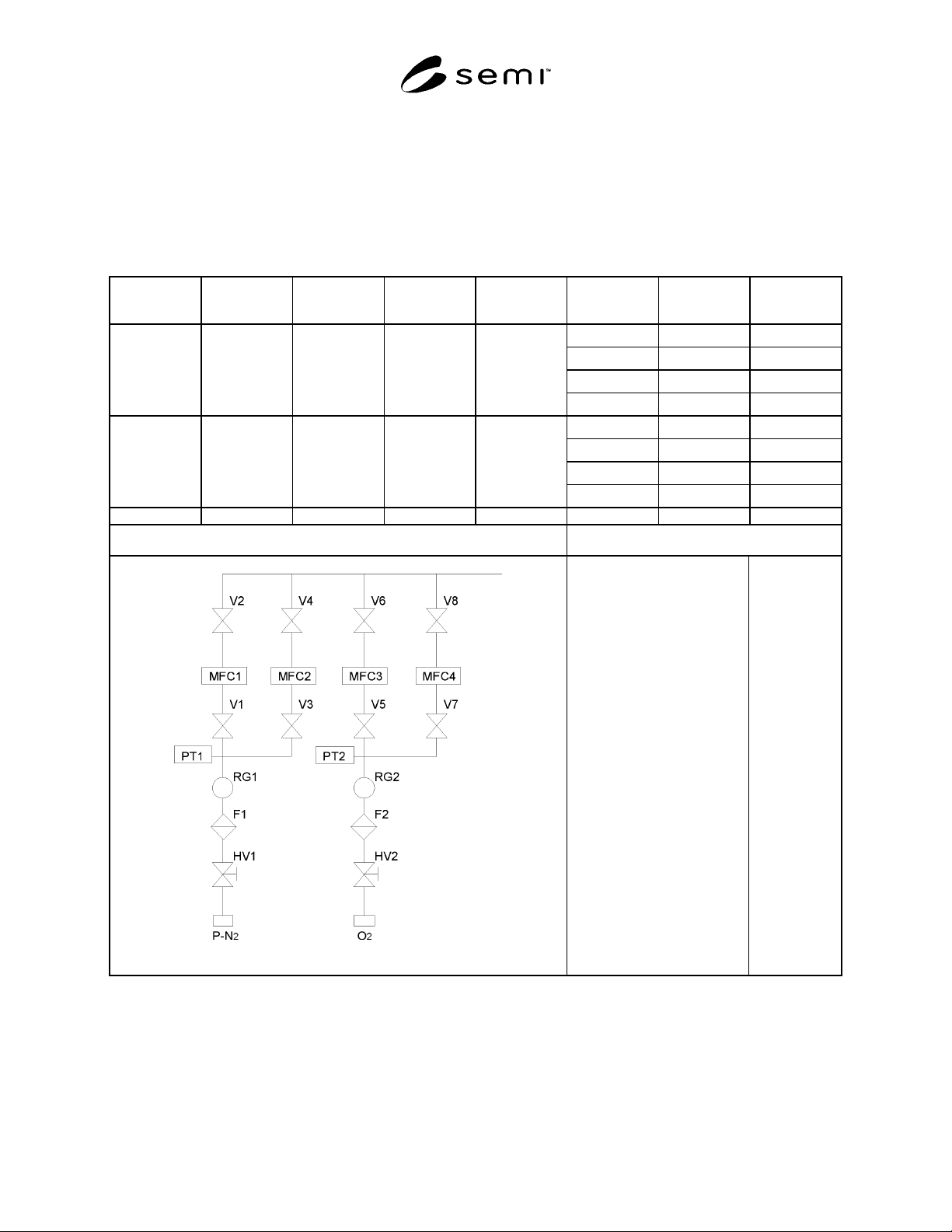
SAMPLE REPORT FORMAT FOR PULSE FLOW PARTICLE TEST
NOTE: This appendix is being balloted as an official part of SEMI F70 by full letter ballot procedures, but the
recommendation in this appendix are optional and are not required to conform to this standard.
PULSE FLOW PARTICLE TEST REPORT
Line Design Flow
(l/min)
Test Flow
(l/min)
Sampling
Method
Total Sampling
Volume (l)
Total Particle
Count
Drive Valve # Particle Count
(particle/l)
4
V1
1.4 × 10
-2
3
V2
1.1 × 10
-2
3
V3
1.1 × 10
-2
P-N
2
200 300
Partial
Sampling
141.5
4
V4
1.4 × 10
-2
1
V5
3.5 × 10
-2
1 V6
3.5 × 10
-2
0 V7 0
O
2
0.5 0.75 Full Sampling
28.5
(See NOTE 1.)
1 V8
3.5 × 10
-2
Flow Diagram of System Under Test Test Condition
Counter Type:
Manufacturer of counter
Counter Model
Sample Flow:
Particle Diameter:
Sampler Diameter:
Sample Probe Diameter:
Test gas:
Background Count
Valve Operation Interval:
LPC
A
B
28.3 l/min
≥ 0.1 µ m
30.0 mm
7.53 mm
LN
2
0
30 cycle/
minute
NOTE 1. The test period for O2 line was extended to 76 minutes in order that the total volume of the test flow achieves more than 28.3 liters.