semi合集-English.pdf - 第4188页
SEMI F71-1102 © SEMI 2002 3 8 Reporting Results 8.1 The report shall include the following: • Date and time of test, • Operator, • Leak point and leak rate, • Helium leak detector m aker and model number, • Flow diagram …
SEMI F71-1102 © SEMI 2002 2
7.2 Perform the helium leak test and confirm whether
there is leakage in the gas panel before starting
temperature cycle examination. Connect all flow path
in the gas panel to helium leak detector and plug all
open end connections before the helium leak test is
executed. Abort testing if leakage is detected and record
leaking points and leak rate.
7.3 Put the test sample in the constant temperature
oven and apply heat until the test sample reaches T-
max. Maintain the temperature for 10 ± 1 minutes.
7.4 Remove the sample from the constant temperature
oven and cool down to the room temperature and
perform helium leak test.
7.5 Put the test sample in the freezer and cool until the
test sample reaches T-min. Maintain the temperature
for 10 ± 1 minutes.
7.6 Remove the sample from the freezer and
equilibrate to the room temperature and perform helium
leak test .
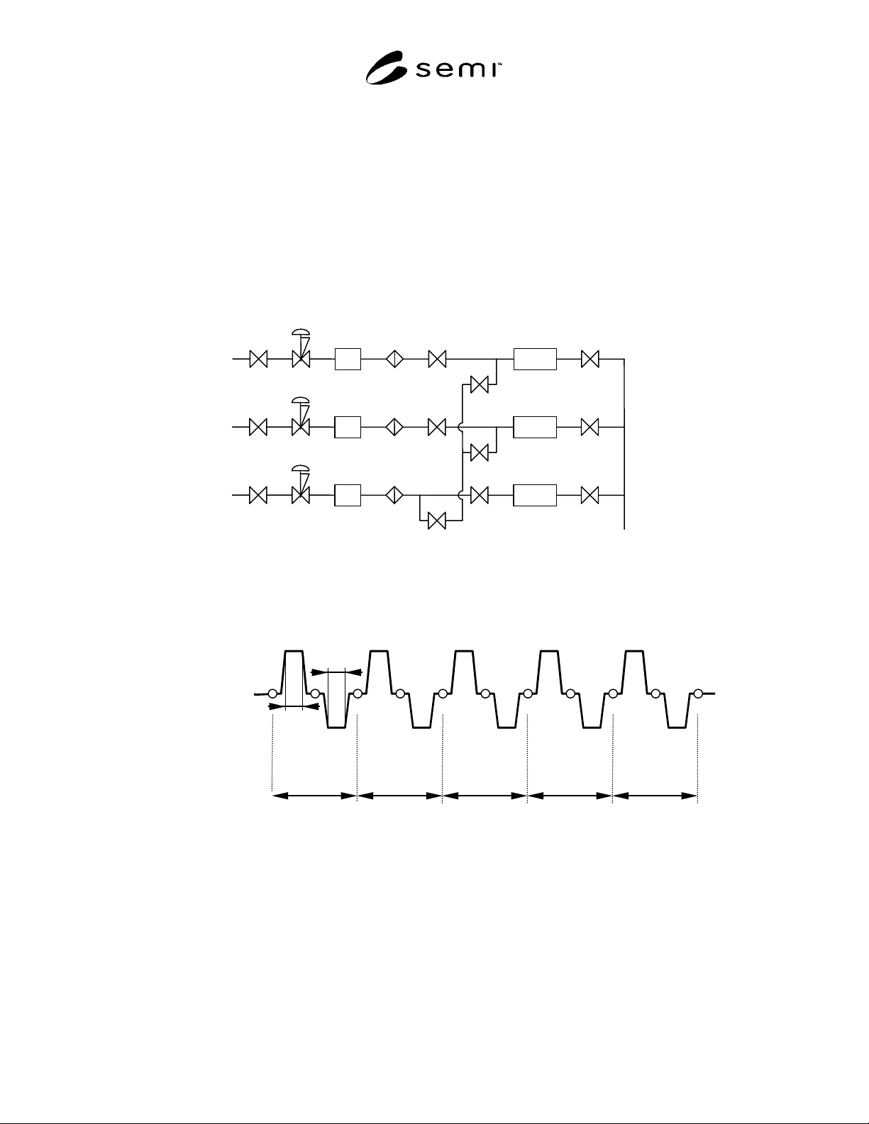
7.7 Repeat Section 7.2 through 7.6 for 5 cycles. The
temperature cycles should be recorded and plotted as
shown in Figure 2.
MFCPT
MFCPT
MFCPT
Figure 1
Typical Gas Delivery System Configuration
R.T. (22 ± 4)
T-max
T-min
10 M
10 M
1 cycle 3 cycle 5 cycle 2 cycle 4 cycle
Figure 2
Temperature Cycle Chart

SEMI F71-1102 © SEMI 2002 3
8 Reporting Results
8.1 The report shall include the following:
• Date and time of test,
• Operator,
• Leak point and leak rate,
• Helium leak detector maker and model number,
• Flow diagram of the test gas panel and layout
drawing,
• Schematic of the test system,
• Temperature conditions of the temperature cycle
test, and
• Any deviations from the test procedure in section
7.
A sample report format is given in Appendix 1.
SEMI F71-1102 © SEMI 2002 4
APPENDIX 1
SAMPLE REPORT FORM
NOTE: The material in this appendix is an official part of SEMI [insert designation, without publication date
(month-year) code] and was approved by full letter ballot procedures on July 19, 2002
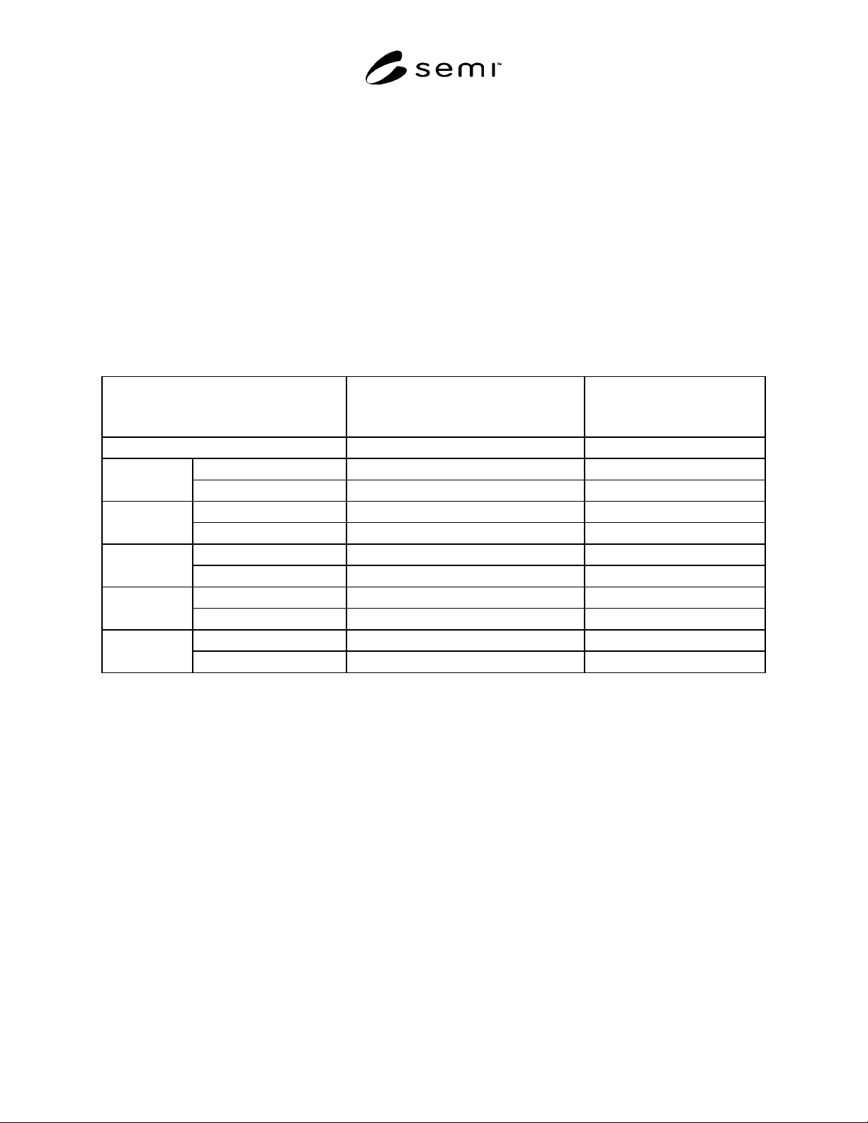
A1-1 Sample Report Form
Test date:
Test operator:
Helium leak detector maker and model number:
Table A1-1 TEMPERATURE CYCLE TEST REPORT
Number of Heat Cycle
Leak Point and Leak Rate
(Pa × m
3
/sec)
Background
(Pa × m
3
/sec)
Initial N.D. 3.6 × 10
-11
after heating (T-max) N.D. 3.1 × 10
-11
1
after cooling (T-min) N.D. 4.1 × 10
-11
after heating (T-max) N.D. 2.6 × 10
-11
2
after cooling (T-min) N.D 3.3 × 10
-11
after heating (T-max) N.D. 4.3 × 10
-11
3
after cooling (T-min) N.D. 3.0 × 10
-11
after heating (T-max) N.D. 2.1 × 10
-11
4
after cooling (T-min) N.D. 1.6 × 10
-11
after heating (T-max) N.D. 2.5 × 10
-11
5
after cooling (T-min) N.D. 3.0 × 10
-11
NOTICE: SEMI makes no warranties or representations as to the suitability of the standards set forth herein for any
particular application. The determination of the suitability of the standard is solely the responsibility of the user.
Users are cautioned to refer to manufacturer’s instructions, product labels, product data sheets, and other relevant
literature respecting any materials mentioned herein. These standards are subject to change without notice.
The user’s attention is called to the possibility that compliance with this standard may require use of copyrighted
material or of an invention covered by patent rights. By publication of this standard, SEMI takes no position
respecting the validity of any patent rights or copyrights asserted in connection with any item mentioned in this
standard. Users of this standard are expressly advised that determination of any such patent rights or copyrights, and
the risk of infringement of such rights, are entirely their own responsibility.
Copyright by SEMI® (Semiconductor Equipment and Materials
International), 3081 Zanker Road, San Jose, CA 95134. Reproduction o
f
the contents in whole or in part is forbidden without express written
consent of SEMI.