semi合集-English.pdf - 第4240页
SEMI F76-0303 © SEMI 2003 4 measured on the analyzer should be reco rded. This level must be 100 ppm ± 10 ppm or t he test cannot proceed. 11.5 Following eac h test, the section of tubing between V3, V4 and the test piec…
SEMI F76-0303 © SEMI 2003 3
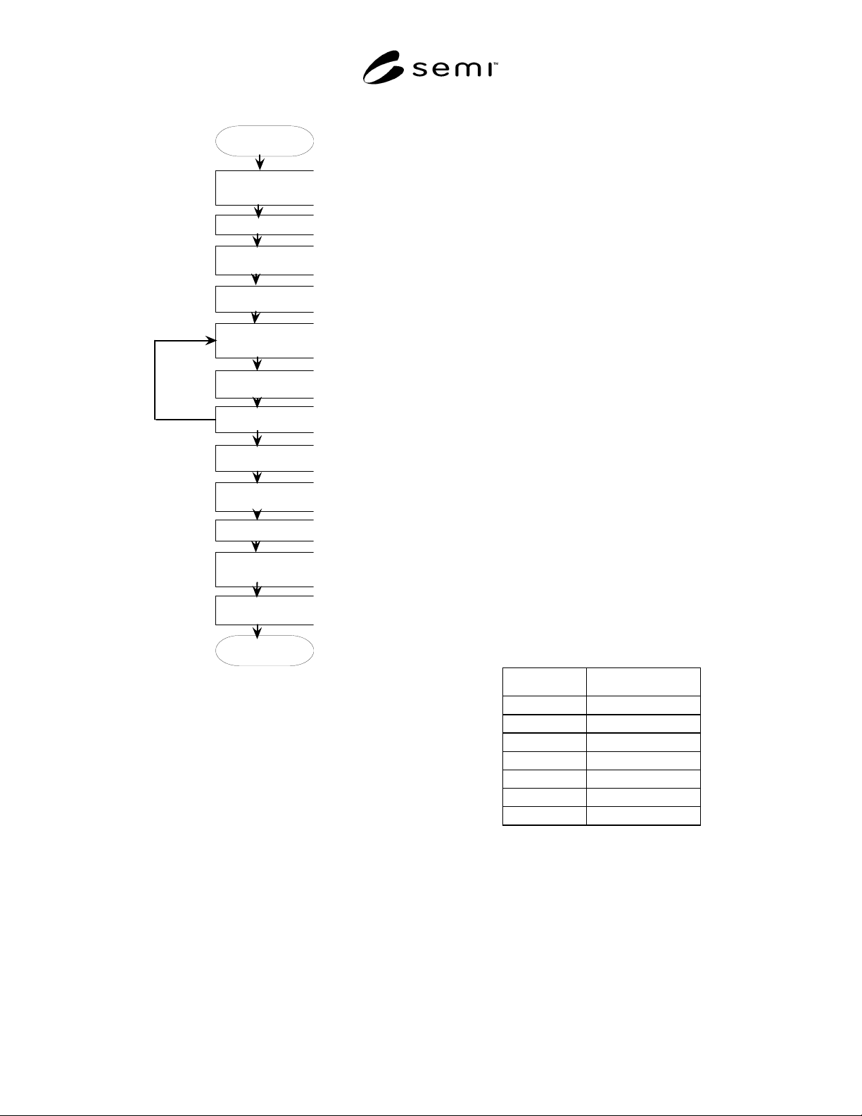
PARTICLE
CLEANLINESS TEST
REPEAT FOR A TOTAL
OF 8 TIMES
HOLD STATIC IN HCl
FOR 16 HOURS
RUN EXPOSURE
SEQUENCE ONCE
PER HOUR 6 TIMES
COOL OVERNIGHT
UNDER N2 PURGE
BAKE 2 HOURS
UNDER N2
INSTALL IN SYSTEM
START
FINAL DRY N2 PURGE
CYCLE PURGE 30
CYCLES
DRY N2 PURGE FOR
2 HOURS
EVALUATE PARTCLE
CLEANLINESS IN N2
REMOVE AND CAP
SAMPLE IN GLOVE
BAG
DONE
Figure 2
Test Flow
9 Safety Precautions
9.1 This method involves the use of hazardous
materials. The user should be experienced in the
handling and use of corrosive specialty gases.
9.2 Safety precautions should include, but are not
limited to:
• continuous air monitoring for HCl in the working
environment as well as the ventilated enclosure.
• SCBA or other supplied air respiratory protection
capable of use in gas exposure levels that may
exceed immediately dangerous to life and health
(IDLH) levels should be used during cylinder
installation and start-up.
• Complete enclosure of the HCl exposure apparatus
in a forced-ventilation cabinet.
• The user should consult the safety, health and
environmental personnel at their site for advice on
appropriate personal protective equipment,
monitoring and ventilation requirements.
10 Test Specimen
10.1 Starting Condition — The test specimen should
be a new component in its original packaging as
supplied by the manufacturer.
10.2 Fittings — The component must have either 1/4″
face seal connections or be of a surface mount design
with all metal seals.
10.3 Sample Size — The number of samples to be
tested is to be determined by the user depending upon
their test objectives. It is beyond the scope of this
method to determine a statistically valid sample size,
however it is recommend that multiple samples of each
type are tested.
11 Preparation of Apparatus
11.1 Mass Spectrometer-based leak checking of the
HCl exposure system after assembly, after the
installation of each test component and after opening
any connection.
11.2 Before each experiment and during idle times, the
apparatus is to be kept in a constant purge condition.
The following valve positions would apply during idle
times:
VALVE POSITION
V1 CLOSED
V2 OPEN
V3 OPEN
V4 CLOSED
V5 OPEN
V6 CLOSED
V7 OPEN
11.3 Moisture Stabilization — At least four hours prior
to the start of a test, a constant flow of wet nitrogen
(100 ppm H
2
O) should be established through the
sampling port so as to maintain a steady moisture
output from the moisture generator. This is
accomplished by opening valve V7. During this time,
V4 is closed.
11.4 Moisture Level Verification — Once the moisture
level is stabilized in Section 11.2, the moisture value
SEMI F76-0303 © SEMI 2003 4
measured on the analyzer should be recorded. This
level must be 100 ppm ± 10 ppm or the test cannot
proceed.
11.5 Following each test, the section of tubing between
V3, V4 and the test piece must be replaced. This will
minimize the particle contribution from the system due
to system corrosion.
12 Calibration
12.1 Calibration of the mass flow controllers should be
performed according to manufacturers
recommendations. The permeation source used in the
moisture generator should be provided with
documentation of permeation rate.
13 Procedure
13.1 Baseline Particle Cleanliness Evaluation — A
particle cleanliness evaluation is to be conducted on
each component before installation into the HCl
exposure system. The baseline particle cleanliness
evaluation is to be conducted on new components
according to one of the following test methods:
13.1.1 Low Pressure Regulators — SEMASPEC
#93021510A-STD — Test Method for Determination
of Particle Contribution by Low Pressure Regulators in
Gas Distribution Systems.
13.1.2 Valves — ASTM F1394-92 — Standard Test
Method for Determination of Particle Contribution from
Gas Distribution System Valves.
13.1.3 Filters — SEMASPEC #93021511A — Test
Method for Determination of Particle Contribution by
Filters in Gas Distribution Systems.
13.2 Install sample in system while maintaining a
continuous nitrogen purge of 500 sccm.
13.3 Bake the sample for two hours. Filters will be
baked at 100°C and valves and regulators will be baked
at 70°C. Maintain a continuous N
2
purge during
baking. Valves and regulators will be in the full open
position.
13.4 Cool sample overnight under N
2
purge of 500
sccm. From this point on, the sample remains at room
temperature.
13.5 Run HCl exposure sequence once per hour six
times.
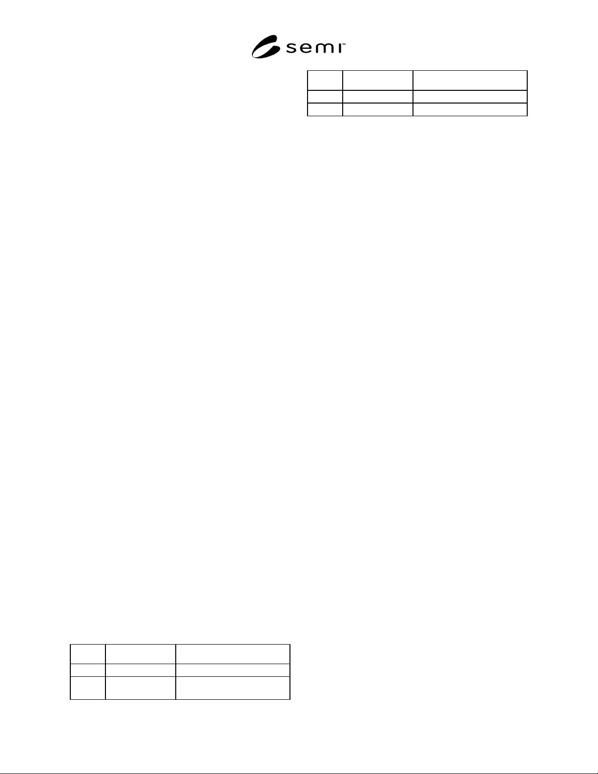
Table 1 HCl Exposure Sequence
STEP TIME CONDITION
1 5 minutes Flow dry N
2
, 0.5 slm
2 10 minutes Flow wet N
2
- 100 ppm
H
2
O, 0.5 slm
STEP TIME CONDITION
3 5 minutes Flow dry HCl, 0.5 slm
4 40 minutes Stagnant HCl, no flow
13.6 Hold sample in static HCl (no flow) for 16 hours.
13.7 Repeat Sections 13.5 and 13.6 for a total of 8
times. This will require a number of days to complete.
If this involves a weekend or a period of time when the
test must be temporarily suspended, then a dry N
2
flow
must be resumed while in this idle mode (see Section
11.1). Flow is not to be interrupted prior to completion
of Section 13.6.
13.8 The test should not be interrupted immediately
prior to moving to the particle testing, Section 13.9.
13.9 Purge with dry N
2
for 2 hours at 500 sccm.
13.10 Cycle purge for 30 cycles. The cycle purge
consists of 20 seconds of rough vacuum 85000 pascals
(25” Hg) and 10 seconds of pressurization with dry N
2
to 5.5 × 10
5
pascals (80 psig).
13.11 Final Dry N
2
Purge — The component is purged
with dry N
2
according to the following schedule: 4
hours for a valve or regulator, and 24 hours for a filter.
13.12 With a purged glove bag around the sample,
remove it into the glove bag and cap both ends. The
sample can now be removed from the glove bag and
transferred to the particle test stand.
13.13 Final Particle Test in Nitrogen
13.13.1 Place a purged glove bag on the particle test
apparatus at the sample installation point.
13.13.2 Place the sample inside the glove bag and only
then remove the caps and install the sample in the
system.
13.13.3 Carry out the particle test according to the
methods cited in Section 13.1.
14 Reporting Results
14.1 Data Presentation — Particle data should be
plotted for each component on a single graph according
to the methods cited in Section 13.1. Both the before
HCl exposure and after HCl exposure data should be
plotted on the same graph.
14.2 Other Information — Other information to be
included in the report:
• sample make, model and serial number,
• date of test,
• person who conducted test,

SEMI F76-0303 © SEMI 2003 5
• last calibration date of CNC,
• age of moisture permeation source,
• measured moisture concentration at valve V7,
• ambient temperature and relative humidity, and
• record all exposure times, temperatures, and flow
rates from each of the exposure events.
15 Related Documents
15.1 SEMI Standards
SEMI F55 — Test Method for Determining the
Corrosion Resistance of Mass Flow Controllers
15.2 SEMATECH Documents
3
SEMASPEC #90120390B-STD — Test Method for
Determination of Particle Contribution by Valves in
Gas Distribution Systems.
SEMASPEC #92071233B-STD — “SEMASPEC
Provisional Test Method for Determining the Corrosion
Resistance of Mass Flow Controllers,” February 5,
1993.
15.3 Other
Hwa-Chi Wang, Govind Doddi, and Stephen Chesters,
“Comparative Corrosion Studies for HCl - and HBr-
Gas Distribution Systems,” 1995 Proceedings - Institute
of Environmental Sciences.
Journal of the IES — “Estimating the Lifetime of
Electropolished Stainless Steel (EPSS) Tubing in
Corrosive Gas Services”, July/Aug. 1994.
The Electrochemical Society, Inc. — “The Role of
Moisture in Corrosion of HBr Gas Distribution
Systems”, April 1995.
3 SEMATECH, 2706 Montopolis Drive, Austin, TX 78741, website:
www.sematech.org
NOTICE: SEMI makes no warranties or
representations as to the suitability of the standards set
forth herein for any particular application. The
determination of the suitability of the standard is solely
the responsibility of the user. Users are cautioned to
refer to manufacturer’s instructions, product labels,
product data sheets, and other relevant literature
respecting any materials mentioned herein. These
standards are subject to change without notice.
The user’s attention is called to the possibility that
compliance with this standard may require use of
copyrighted material or of an invention covered by
patent rights. By publication of this standard, SEMI
takes no position respecting the validity of any patent
rights or copyrights asserted in connection with any
item mentioned in this standard. Users of this standard
are expressly advised that determination of any such
patent rights or copyrights, and the risk of infringement
of such rights, are entirely their own responsibility.
Copyright by SEMI® (Semiconductor Equipment and Materials
International), 3081 Zanker Road, San Jose, CA 95134. Reproduction o
f
the contents in whole or in part is forbidden without express written
consent of SEMI.