semi合集-English.pdf - 第4284页
SEMI F80-1103 © SEMI 2003 4 7.2 Case (2) — This is the test method in consideration of gas change i n the gas delivery system . 7.2.1 A recommended test fl ow schematic is sho wn in Figure 8. 7.2.2 The test is t o evalua…
SEMI F80-1103 © SEMI 2003 3
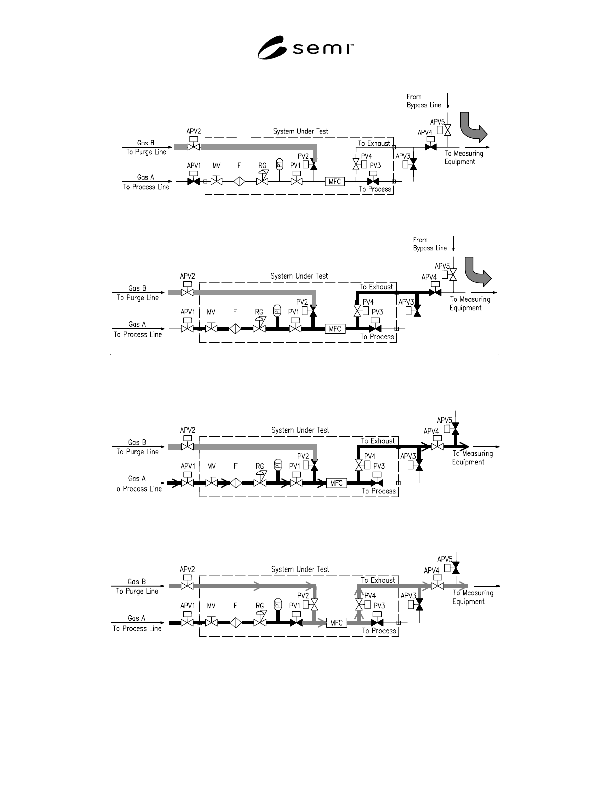
(3)
Figure 4
Procedure 7.1.5
(4)
Figure 5
Procedure 7.1.6
Figure 6
Procedure 7.1.7
Figure 7
Procedure 7.1.8
SEMI F80-1103 © SEMI 2003 4
7.2 Case (2) — This is the test method in consideration
of gas change in the gas delivery system.
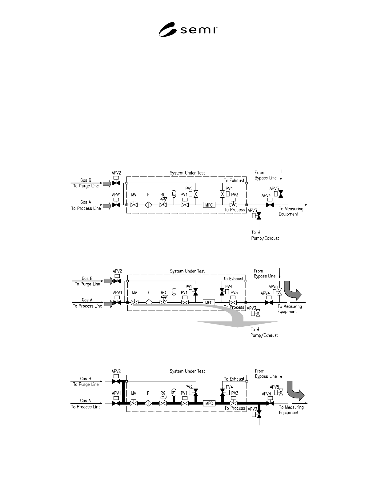
7.2.1 A recommended test flow schematic is shown in
Figure 8.
7.2.2 The test is to evaluate a gas change performance
in the gas delivery systems by using process line.
7.2.3 Set each component for the following condition
before starting the test. APV1, APV2, APV3, APV4,
and APV5 are closed condition. Rest of the components
in the System Under Test are open condition. Supply
Gas A to the upstream of APV1. Supply Gas B to the
upstream of APV2. (See Figure 8.)
7.2.4 Open APV5 and flow Gas A from Bypass line.
(1) Close PV2 and PV4, open APV3, and vacuum the
System Under Test. (2) (See Figure 9.)
7.2.5 (a) Close APV3, open APV1, and flow Gas A to
process line. (b) Close APV1, open APV3, and vacuum
process line. Then, close APV3, open and close APV1,
and open APV3. (c) Repeat this operation (b) 3 times
and close APV3 to sufficiently fill process line with
Gas A. (3) (See Figure 10.)
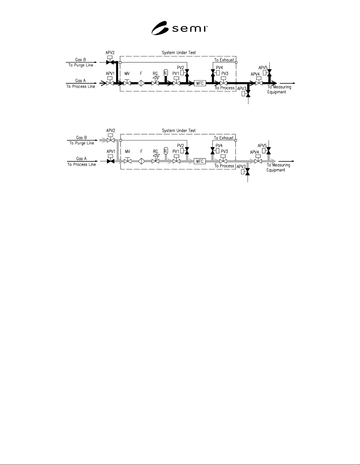
7.2.6 Open APV1and close APV5. Then open APV4
and flow Gas A to the System Under Test. Measure the
concentration of Gas A by measuring equipment. (See
Figure 11.)
7.2.7 Close APV1, open APV2, and flow Gas B to the
System Under Test. The measuring equipment
continuously monitors the Gas A concentration. Record
the time to achieve required concentration for Gas A
from the start of flowing Gas B. (See Figure 12.)
Figure 8
Gas Change/Purge Efficiency Test Schematic Case 2
(1)
(2)
Figure 9
Procedure 7.2.4
(3)
Figure 10
Procedure 7.2.5
SEMI F80-1103 © SEMI 2003 5
Figure 11
Procedure 7.2.6
Figure 12
Procedure 7.2.7
8 Reporting Results
8.1 The following items shall be stated on the test
report.
• Test date and time,
• Name of an operator,
• Test temperature,
• Flow rate of Gas A and Gas B,
• Name of Gas A and Gas B,
• Pressure of Gas A and Gas B,
• Name of the measuring equipment and model,
• Measuring condition of the measuring equipment
(ex. APIMS: Scan time, Mass range, and
measuring range),
• Minimum detectable limit of the measuring
equipment, and
• Relationship between gas concentration and test
time.
NOTICE: SEMI makes no warranties or
representations as to the suitability of the standards set
forth herein for any particular application. The
determination of the suitability of the standard is solely
the responsibility of the user. Users are cautioned to
refer to manufacturer' s instructions, product labels,
product data sheets, and other relevant literature,
respecting any materials or equipment mentioned
herein. These standards are subject to change without
notice.
By publication of this standard, Semiconductor
Equipment and Materials International (SEMI) takes no
position respecting the validity of any patent rights or
copyrights asserted in connection with any items
mentioned in this standard. Users of this standard are
expressly advised that determination of any such patent
rights or copyrights, and the risk of infringement of
such rights are entirely their own responsibility.
Copyright by SEMI® (Semiconductor Equipment and Materials
International), 3081 Zanker Road, San Jose, CA 95134. Reproduction o
f
the contents in whole or in part is forbidden without express written
consent of SEMI.