semi合集-English.pdf - 第437页
SEMI E62-0705 © SEMI 1997, 2005 6 Symbol Used Value Specified Datum Measured from Feature Measured to r 35 30 mm (1.18 in.) maximum not applicab le outside corner of frame seal zone r 36 6.75 ± 0.1 mm (0.266 ± 0.004 in.)…
SEMI E62-0705 © SEMI 1997, 2005 5
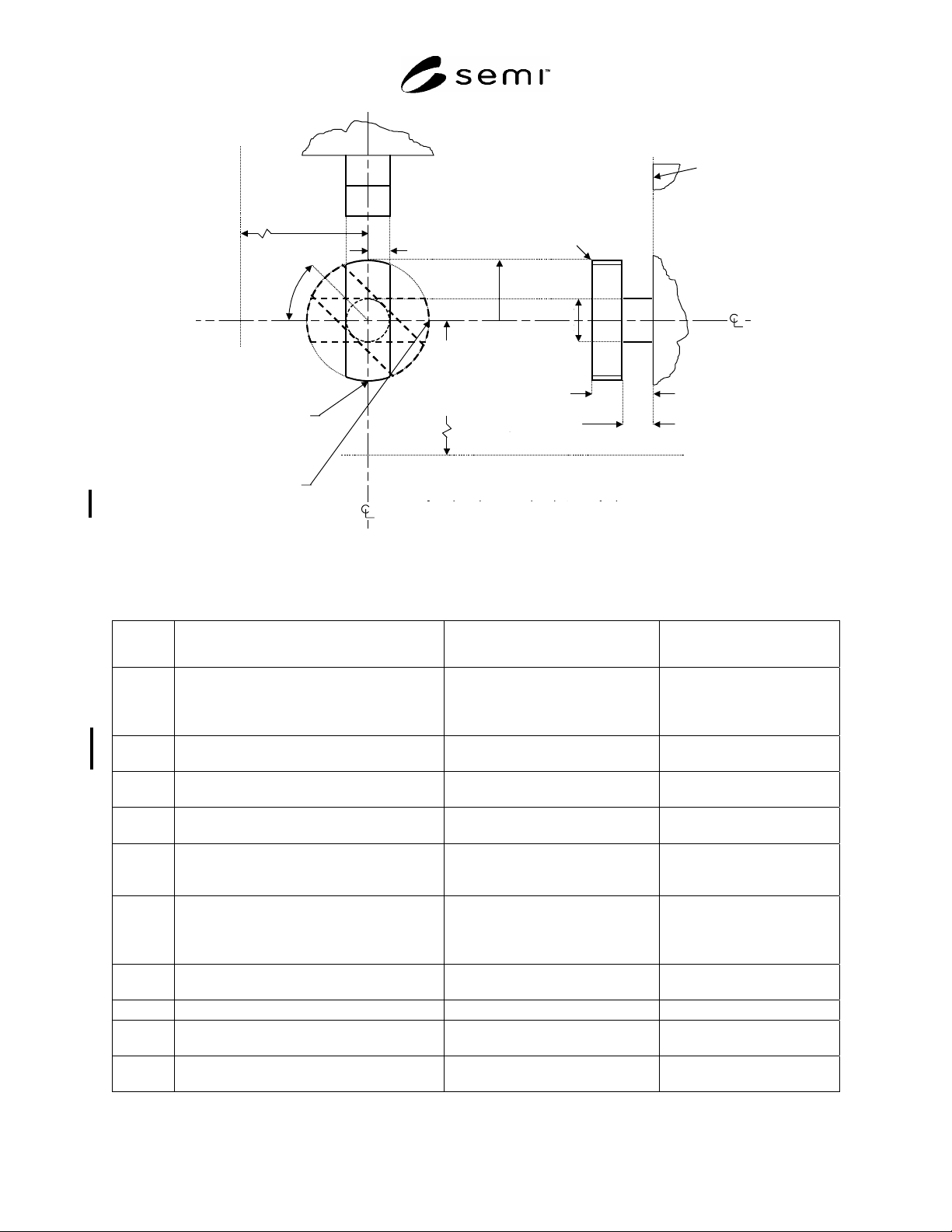
position when
door is latched to
box
( = 90 ± 1°)
position when
door is unlatched
from box
( = 0 ± 1°)
(numbers in parentheses are for 25-wafer
boxes, if different)
[numbers in square brackets are for boxes
with removable cassettes, if different]
y37= 3.5±0.1
y36= 7±0.1
z30
=106.5
(166.5)
[128
(188)]
d37
=5±0.2
bilateral
datum
plane
load port horizontal datum plane
r36
=6.75±0.1
x36 =2.5±0.1
x30=
129±0.1
door
seal zone
r41=1.5±0.2
(blend radius
at edge of
front surface)
x30 =
129 ± 0.1
x
36 = 2.5 ± 0.1
r41 = 1.5 ± 0.2
(blend radius
at edge of
front surface)
r36
= 6.75 ± 0.1
d37
= 5 ± 0.2
y36 = 7 ± 0.1
y
37 = 3.5 ± 0.1
z30
= 106.5
(166.5)
Figure 3
Latch Key Dimensions
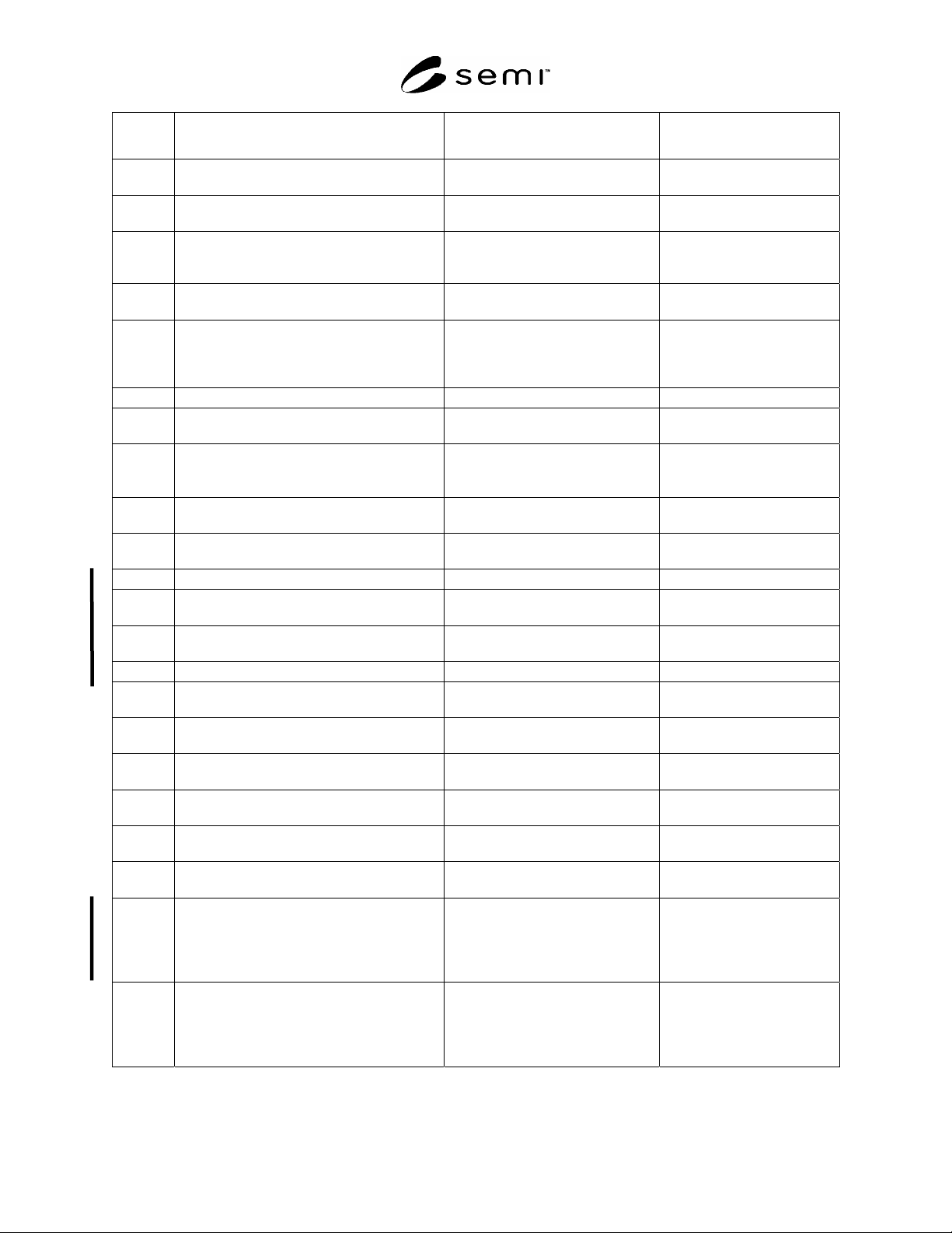
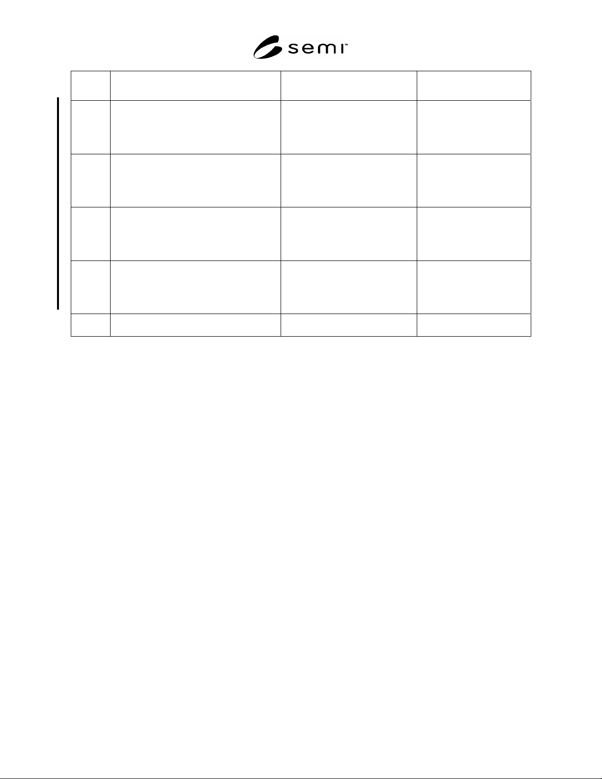
Table 1 Dimensions for Front-Opening Interface Mechanical Specification (FIMS)
Symbol
Used
Value Specified Datum Measured from Feature Measured to
0 ± 1°
(to unlatch the box door from the box)
90 ± 1°
(to latch the box door to the box)
horizontal datum plane clockwise rotation of latch key
d31 9 + 0.02 mm, 0.2 mm
(0.3543 + 0.0008 in. 0.008 in.)
diameter centered on the intersection
of x31 and z31
surface of registration pin shaft
d37 5 ± 0.2 mm
(0.197 ± 0.008 in.)
diameter centered on the intersection
of x30 and z30
surface of latch key shaft
f30 1.7 N-m (15 in.-lbf.) minimum not applicable torque delivered by the port to
turn the latch keys
f34 9 N (2 lbf.) minimum not applicable force with which the port
presses the box door into the
box
f35 20 N (4.5 lbf.) maximum not applicable force per latch key applied to
the FOUP door (in a direction
perpendicular to the facial
datum plane)
r30 5 ± 0.5 mm
(0.20 ± 0.02 in.)
intersection of x31, y31, and z31 shoulder of registration pin
r32 10 mm (0.39 in.) minimum not applicable inside corner of door seal zone
r33 21 ± 0.25 mm
(0.827 ± 0.010 in.)
not applicable outside corner of door seal
zone
r34 23 ± 0.25 mm
(0.906 ± 0.010 in.)
not applicable inside corner of frame seal
zone
SEMI E62-0705 © SEMI 1997, 2005 6
Symbol
Used
Value Specified Datum Measured from Feature Measured to
r35 30 mm (1.18 in.) maximum not applicable outside corner of frame seal
zone
r36 6.75 ± 0.1 mm
(0.266 ± 0.004 in.)
intersection of x30 and z30 ends of latch key head
r38 27.5 mm (1.08 in.) minimum intersection of x31 and z31 boundary of vacuum
application zone around
registration pin
r40 0.4 ± 0.1 mm
(0.016 ± 0.004 in.)
not applicable blend at intersection of r30
with r31 and y32
r41 1.5 ± 0.2 mm
(0.059 ± 0.008 in.)
not applicable
b
lend at convex features on the
outer edge of the latch keys
(adjacent to the surface defined
by y36)
r45 1 mm (0.04 in.) maximum not applicable all concave features (radius)
r46 2 mm (0.08 in.) maximum not applicable all required convex features
(radius)
r47
0.80 m (32 in.)
maximum Roughness (R
a
)
as defined in ISO 4287
not applicable surface finish of the
registration pins and latch keys
x30 129 ± 0.1 mm
(5.08 ± 0.004 in.)
bilateral datum plane center line of latch key rotation
x31 70 ± 0.1 mm
(2.756 ± 0.004 in.)
bilateral datum plane center of registration pins
x32 173.5 mm (6.83 in.) maximum bilateral datum plane inside edge of door seal zone
x33 182.5 ± 0.25 mm
(7.185 ± 0.010 in.)
bilateral datum plane outside edge of door seal zone
x34 184.5 ± 0.25 mm
(7.264 ± 0.010 in.)
bilateral datum plane inside edge of frame seal zone
x35 193.5 mm (7.62 in.) minimum bilateral datum plane outside edge of frame seal zone
x36 2.5 ± 0.1 mm
(0.098 ± 0.004 in.)
x30 from bilateral datum plane side of latch key head
x37 ± 0.2 mm
(± 0.008 in.)
position of the load port door before
opening
position of the load port door
after closing
y31 7.5 mm (0.30 in.) point on door seal zone closest to
facial datum plane
origin of r30 (shoulder radius)
on registration pin
y32 11.0 ± 0.1 mm
(0.43 ± 0.004 in.)
point on door seal zone closest to
facial datum plane
end of registration pin
y36 7.0 ± 0.1 mm
(0.28 ± 0.004 in.)
point on door seal zone closest to
facial datum plane
far side of latch key head
y37 3.5 ± 0.1 mm
(0.14 ± 0.004 in.)
point on door seal zone closest to
facial datum plane
near side of latch key head
z30 106.5 ± 0 mm (4.19 ± 0 in.)
for 13-wafer cassette
and
166.5 ± 0 mm (6.56 ± 0 in.)
for 25-wafer cassette
horizontal datum plane vertical center line of port and
center line of latch key rotation
z31 45 ± 0.1 mm (1.772 ± 0.004 in.)
for 13-wafer cassette
and
105 ± 0.1 mm (4.134 ± 0.004 in.)
for 25-wafer cassette
z30 above horizontal datum plane center of registration pins
SEMI E62-0705 © SEMI 1997, 2005 7
Symbol
Used
Value Specified Datum Measured from Feature Measured to
z32 84.5 mm (3.33 in.) maximum
for 13-wafer cassette
and
144.5 mm (5.69 in.) maximum
for 25-wafer cassette
z30 above horizontal datum plane inside edge of door seal zone
z33 93.5 ± 0.25 mm (3.681 ± 0.010 in.)
for 13-wafer cassette
and
153.5 ± 0.25 mm (6.043 ± 0.010 in.)
for 25-wafer cassette
z30 above horizontal datum plane outside edge of door seal zone
z34 95.5 ± 0.25 mm (3.760 ± 0.010 in.)
for 13-wafer cassette
and
155.5 ± 0.25 mm (6.122 ± 0.010 in.)
for 25-wafer cassette
z30 above horizontal datum plane inside edge of frame seal zone
z35 104.5 mm (4.11 in.) minimum
for 13-wafer cassette
and
164.5 mm (6.48 in.) minimum
for 25-wafer cassette
z30 above horizontal datum plane outside edge of frame seal
zone
z37 ± 0.2 mm
(± 0.008 in.)
position of the load port door before
opening
position of the load port door
after closing