semi合集-English.pdf - 第4398页
SEMI F97-0305 © SEMI 2005 8 9.2 FPU Requirements 9.2.1 The FPU shall be able t o run witho ut a FMCS and shall communicat e a minimal am ount of status informati on to FMCS via t h e networ k as described in the next sec…
SEMI F97-0305 © SEMI 2005 7
8.6 Parameter Definitions
8.6.1 When calling an operation, parameters can be passed and returned. Parameters to be passed and returned
depend upon the operation that is called. By using a parameter definition table the parameters passed and returned
by an operation are defined.
Parameter Description Direction Data Type
8.6.2 Parameter — Within the parameter column the name of the specific parameter is given.
8.6.3 Description — Contains a description of a parameter.
8.6.4 Direction — Defines the direction:
FMCS -> FPU: originated by FMCS and received by FPU
FPU -> FMCS: originated by FPU and received by FMCS
8.6.5 Data Type — Defines the format of a parameter.
8.7 Field Definitions
8.7.1 A parameter can consist of different fields that define the contents of a parameter. A field definition table
defines the format of the fields maintained within a specific parameter.
Field Bit Meaning Mandatory/optional
8.7.2 Field — A parameter can consist of different fields representing the contents of a parameter. Within the field
column the name of the specific field is given.
8.7.3 Bit — In case a field is stored within a bitwise-formatted parameter, the bit column defines the bit number or
bit range where the field value is stored.
8.7.4 Meaning — Defines the meaning of the one or several field values.
8.7.5 Mandatory/Optional — Defines if setting the value of a field is either mandatory or optional.
9 Requirements
9.1 Interconnection between FMCS and FPUs
9.1.1 The interconnection between the FMCS and the FPUs may be made by any type of bus system specified by
SEMI (e.g. SEMI E54 series) as well as industrial ethernet based networks. It is the purpose of this standard:
to specify the semantics of the services that are exchanged between the FMCS and the FPUs, and
to model the status information of the state machines that are maintained by the FPUs.
9.1.2 As introduced in §7, state models are used to represent the current state of a FPU. The FMCS may use this
state information in order to display the state of all FPUs. In addition, the FMCS may decide based on the state of a
FPU whether remote operations on a FPU are advisable or not.
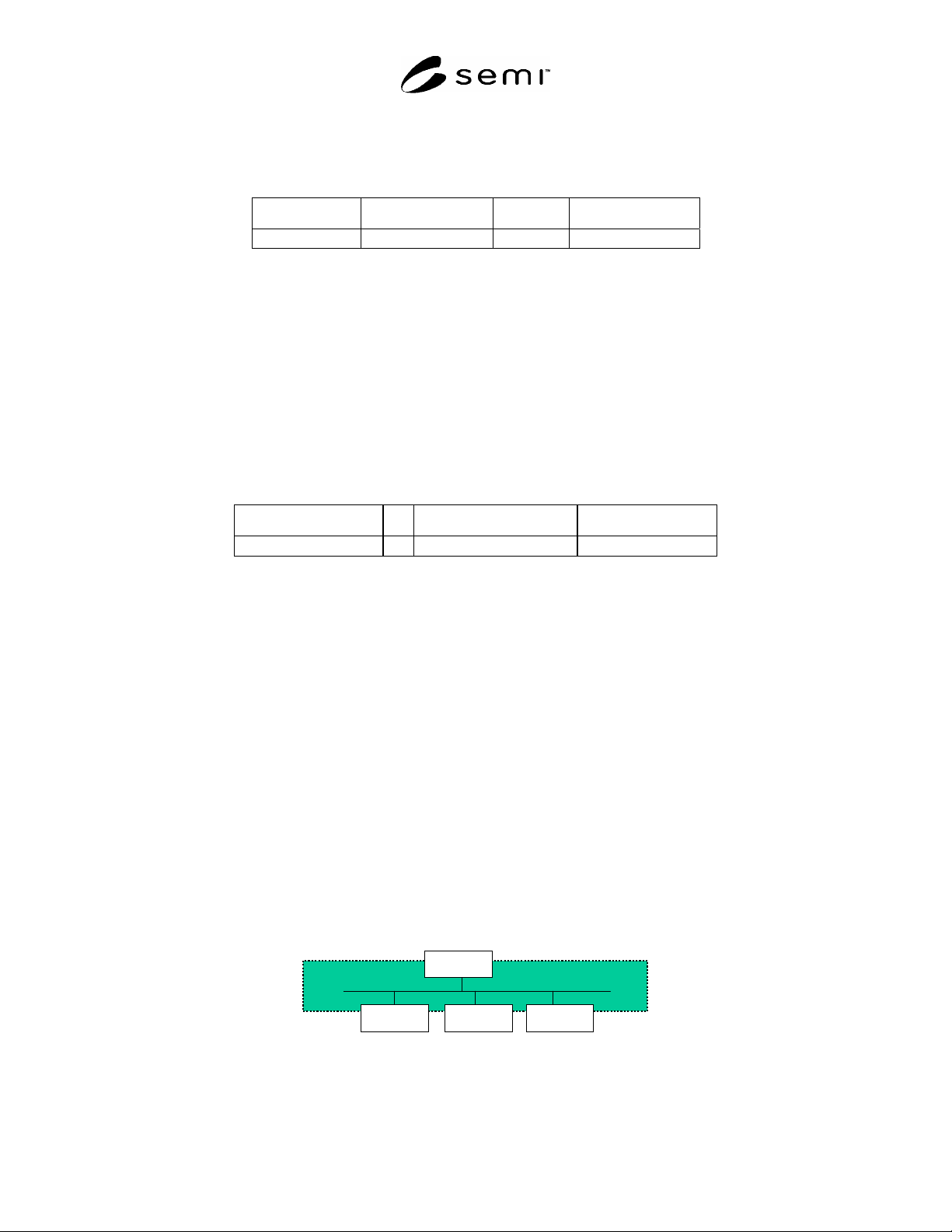
FMCS
FPU 1 FPU 2 FPU n
FMCS
FPU 1 FPU 2 FPU n
Figure 3
Interconnection Between FMCS and FPUs
SEMI F97-0305 © SEMI 2005 8
9.2 FPU Requirements
9.2.1 The FPU shall be able to run without a FMCS and shall communicate a minimal amount of status information
to FMCS via the network as described in the next section.
9.3 FMCS Requirements
9.3.1 The FMCS shall be able to support the interface to the FPU and to make the information of this interface
available through the Data Cache of the FMCS. The FMCS shall be able to either monitor and/or control the FPU
depending on the application.
9.4 State Models of Facility Package Unit
9.4.1 State Models are used to describe the status of the FPU. For the definition of the status models see §8. In the
following all status values are specified together with their transitions.
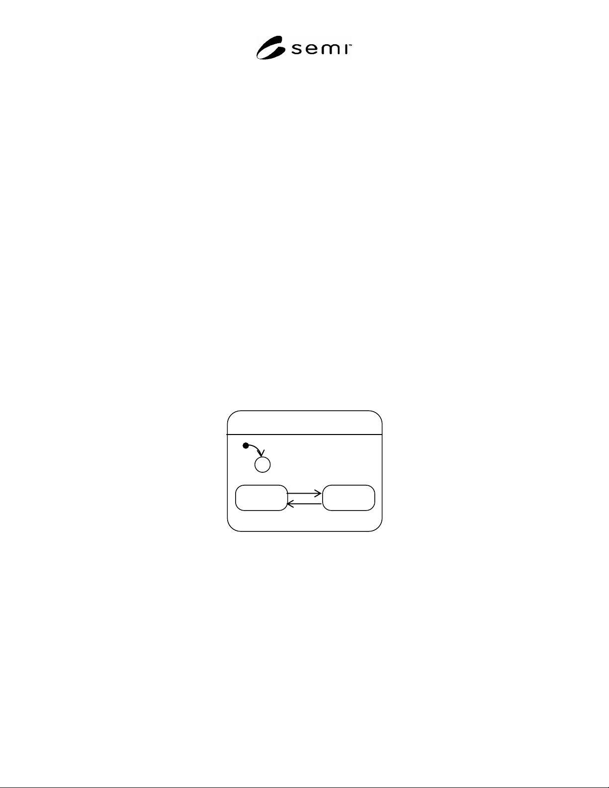
9.4.2 Watchdog-Toggle
9.4.2.1 The Watchdog-toggle shall be used to signal that a FPU still is capable to perform its processing function
and is able to notify this to the FMCS. As long as the toggle mechanism alternates between “on” and “off” the
processing function of the FPU is assumed to be functional. The processing function is assumed to be a
programmed function, e.g. for a PLC. The toggle mechanism shall be linked into the processing function of the FPU
so that if the processing function stops, the toggle mechanism will stop as well. Watchdog-toggle represents a
variable that toggles its value between “0” and “1” within a specified time window. The maximum required cycle
time shall not exceed one minute. The Watchdog-toggle is used to realize a “life-beat monitoring function”.
9.4.2.2 The Watchdog-toggle is always required except
in the case that the underlying communication system of the FPU and the FMCS already provides an integrated
life-beat function, or
the FPU is a very simple device which does not provide any processing function (e.g., a valve, electrical engine
or heater).
Watchdog-Toggle
On Off
2
3
C
1
Figure 4
State Transition Diagram Watchdog-Toggle
SEMI F97-0305 © SEMI 2005 9
Table 1 State Transition for Watchdog-Toggle
Number Previous State Trigger New State Actions Remark
1 (no state) Start up of FPU. On or Off Timer is set to expire for
the next time period.
Dependent on
Implementation.
2 On Timer expired. Off Timer is set to expire for
the next time period.
3 Off Timer expired. On Timer is set to expire for
the next time period.
9.4.3 OP-Mode
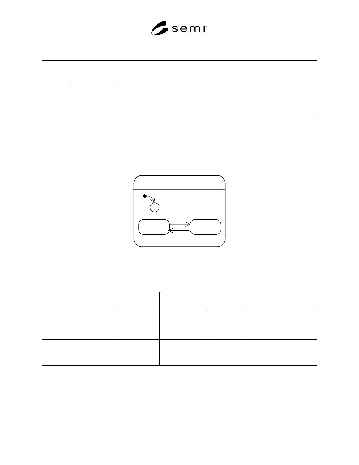
9.4.3.1 OP-Mode specifies the operation mode of the FPU. It can assume two values: Manual and Automatic. The
behavior of the FPU with respect to the states Manual and Automatic is out of scope.
Manual: FPU operates in manual mode.
Automatic: FPU operates in automatic mode.
OP-Mode
Manual Automatic
2
3
C
1
Figure 5
State Transition Diagram OP-Mode
Table 2 State Transition Table for OP-Mode
Number Previous State Trigger New State Actions Remark
1 (no state) Start up of FPU. Manual or Automatic None. Dependent on type of FPU.
2 Manual Trigger to switch
to Automatic.
Automatic FPU performs its
automatic
functions.
Trigger may be caused by:
manual operator action
or automatic trigger by a
programmed logic.
3 Automatic Trigger to switch
to Manual.
Manual FPU stops its
automatic
functions.
Trigger may be caused by:
manual operator action
or automatic trigger by a
programmed logic.
9.4.4 Control-Mode
9.4.4.1 Control-Mode specifies the control mode of the FPU with respect to the FMCS. It may assume two values:
Local and Remote. The behavior of the FPU with respect to the states Local and Remote is out of scope. It is
dependent on the type of FPU. Control Mode is intended to be used by the FMCS to identify whether a remote
operation of the FPU is enabled or disabled – by this the FMCS can allow or disallow operator actions on the FMCS