semi合集-English.pdf - 第4422页
SEMI F98-0305 © SEMI 2005 5 NOTICE: SEMI makes no warranties or represen tations as to the suitability o f the standards set forth herein for any particular application. The determination of the suitability of the standa…
SEMI F98-0305 © SEMI 2005 4
analyzers at a sufficient distance upstream of the central diverter point, or provide a sufficient buffer/quarantine
volume.
8.3 Temperature — Hot water effluent from rinse tanks on wet benches can provide a challenge in recycling
treatment systems, as temperature can be an important variable to water recycling system performance and can cause
an increase in bacteria growth. This issue is influenced by seasonal variations in ambient temperature. Heat
exchangers for process waters can be added to a recycle system in order to keep the system at a steady state.
8.4 Discharge Permits — One aspect of water reuse that can have significant economic impact relates to site
effluent and local discharge permits. As water reuse increases, contaminant concentrations in the site effluent will
also increase due to the reduced volume of the wastewater. If site water reuse is great enough, these higher
concentrations may approach the limits of the local wastewater discharge permits and need to be closely monitored.
9 Economic Considerations
9.1 General — Potential cost savings are available from the introduction of reuse water systems. One type of
savings can be measured from the actual cost of the water being replaced. The cost savings depends on the grade of
water being replaced and the original cost of producing that grade of water at that location. Additional savings can
often be realized in maintenance costs (e.g. membrane cleaning) given that the reclaim water is generally of better
quality than incoming water. Models for evaluating the economics of a reclaim or recycle water application have
been developed in the industry.
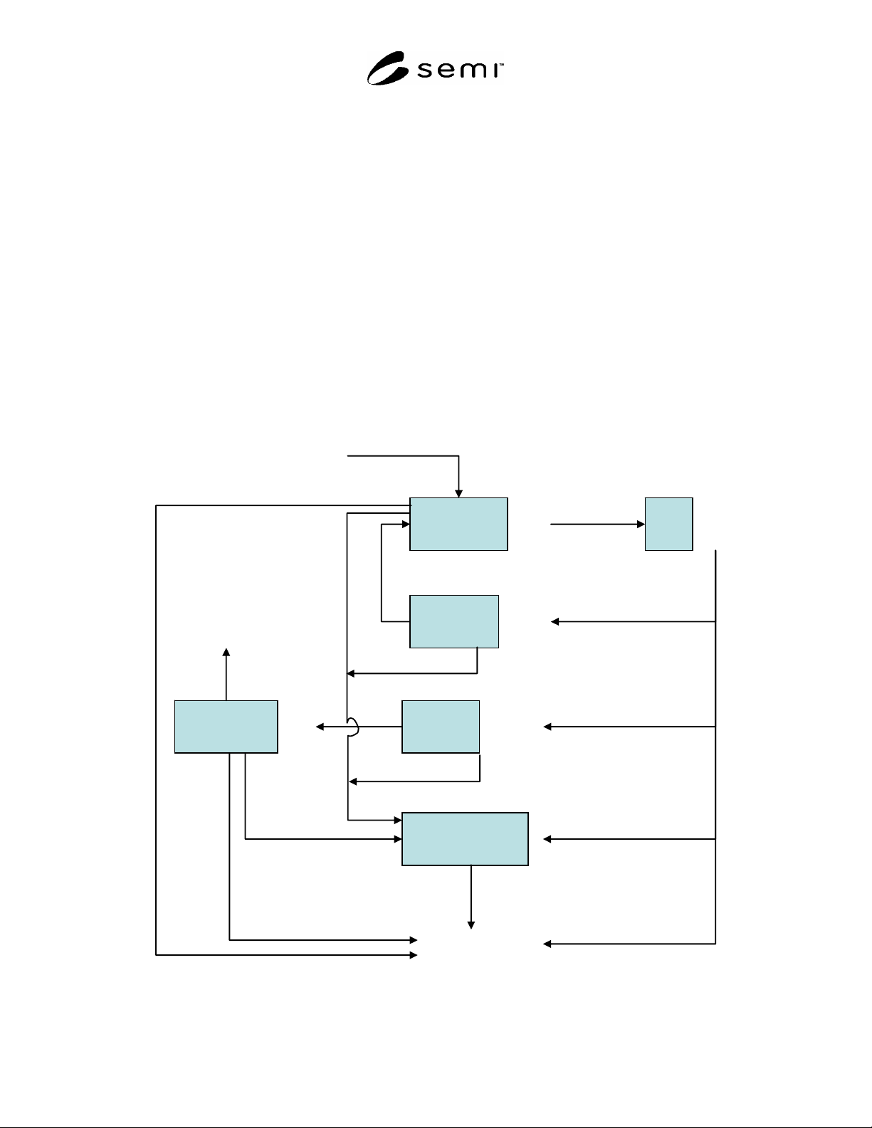
UPW Plant
Recycling
Plant
Fab
Reclaim
Plant
Other users
Waste water
treatment plant
Waste water
Lightly
contaminated
Contaminated
Very
contaminated
Raw water
NOTE: Courtesy of German UPW standard VDI 2083 Part 13
Figure 1
Schematic of Basic Reclaim Water System

SEMI F98-0305 © SEMI 2005 5
NOTICE: SEMI makes no warranties or representations as to the suitability of the standards set forth herein for any
particular application. The determination of the suitability of the standard is solely the responsibility of the user.
Users are cautioned to refer to manufacturer's instructions, product labels, product data sheets, and other relevant
literature, respecting any materials or equipment mentioned herein. These standards are subject to change without
notice.
By publication of this standard, Semiconductor Equipment and Materials International (SEMI) takes no position
respecting the validity of any patent rights or copyrights asserted in connection with any items mentioned in this
standard. Users of this standard are expressly advised that determination of any such patent rights or copyrights, and
the risk of infringement of such rights are entirely their own responsibility.
Copyright by SEMI® (Semiconductor Equipment and Materials
International), 3081 Zanker Road, San Jose, CA 95134. Reproduction of
the contents in whole or in part is forbidden without express written
fS

SEMI F99-0705 © SEMI 2005 1
SEMI F99-0705
DIMENSIONAL SPECIFICATION OF A DIAPHRAGM VALVE FOR A
METRIC PFA TUBE
This specification was technically approved by the Global Liquid Chemicals Committee. This edition was
approved for publication by the global Audits and Reviews Subcommittee on March 11, 2005. It was
available at www.semi.org in June 2005 and on CD-ROM in July 2005.
1 Purpose
1.1 This document specifies the outside dimensions of diaphragm valves used with metric PFA tubes in liquid
chemical distribution facilities and process equipment for semiconductor and flat panel display manufacturing.
2 Scope
2.1 This specification addresses dimensions of diaphragm valves used with metric PFA tubes except for face-to-
face dimensions. Since there are many seizes of fittings being applied to valves, this document doesn’t specify face-
to-face dimensions.
2.2 These diaphragm valves are limited to pneumatic valves. Specification for manual valves should be separately
provided as needed.
2.3 These diaphragm valves are used in chemical distribution systems for semiconductor and flat panel display
manufacturing.
2.4 The valves are made from materials such as PTFE or PFA, which have high corrosion resistance and low
contamination contribution to the fluid.
2.5 The valves withstand up to 0.2 megapascals (MPa) [29 pounds per square inch (psi)] back pressure.
NOTICE: This standard does not purport to address safety issues, if any, associated with its use. It is the
responsibility of the users of this standard to establish appropriate safety and health practices and determine the
applicability of regulatory or other limitations prior to use.
3 Referenced Standards
3.1 SEMI Standards
SEMI F65 — Dimensional Specification for Mounting Bases of Diaphragm Valves Used with Metric PFA Tubes
NOTICE: Unless otherwise indicated, all documents cited shall be the latest published versions.
4 Terminology
4.1 Abbreviations and Acronyms
4.1.1 PFA — Tetrafluoroethylene Perfluoroalkylvinylether
4.1.2 PTFE — Tetrafluoroethylene
4.2 Definitions
4.2.1 back pressure — a maximum allowable pressure applied to outlet of a diaphragm valve.
4.2.2 liquid chemicals — acid, alkali, organic solvent, and pure water used for wet stations; resists and developers
used for truck system; and other chemicals used for process or maintenance (such as slurry of CMP) of equipment or
facilities.
5 Dimensional Specifications
5.1 Overall Height Dimensions — The height (B) and (C) indicated in Figure 1 and the values for different tube
sizes are specified in Table 1.