semi合集-English.pdf - 第4463页
SEMI D16-0998 © SEMI 1998 2 5.2.11 Z4 — th e hei ght of the ex cl usi o n zone used for PGV cart alignment devices. 5.2.12 Z5 — t he maximum height of t h e protrusion used f or docking devices. 5.2.13 Z6 — the location …

SEMI D16-0998 © SEMI 19981
SEMI D16-0998
SPECIFICATION FOR MECHANICAL INTERFACE BETWEEN FLAT
PANEL DISPLAY MATERIAL HANDLING SYSTEM AND TOOL PORT
This specification was technically approved by the Flat Panel Display Equipment Committee and is the direct
responsibility of the North American Flat Panel Display Committee. Current edition approved by the North
American Regional Stadards Committee July 1998. Published on SEMI OnLine September 1998; print version
published September 1998.
1 Purpose
1.1 This specification defines feature requirements on
and about tool ports of process tools used in
manufacturing of flat panel displays. These feature
requirements facilitate the interfacing of transport
equipment to the tool by standardizing the feature
requirements. Such standards are intended to promote
cost-effective interfacing while preserving freedom of
choice in material handling equipment.
2 Scope
2.1 These standards define mechanical features on or
about the process tool port, and in front of or on the tool
face. Although these features are intended for specific
functions, they do not set design requirements for any
particular functionality. The interface requirements are
meant to be universal and to avoid the promotion of any
particular form of transport. Therefore, they are useful
for the interfacing of continuous direct WIP transports,
such as conveyors, or discrete vehicles of foreseeable
future design, such as AGVs, to the process tool port.
The dimensions incorporated in the standard apply to
single panel handling as well as substrate carriers.
3 Limitations
3.1 Current display manufacturing utilizes several
substrate sizes, many of them “non-standard.” This
proposed interface specification includes dimensions
for the substrate sizes of 550 × 650 mm, and 600 × 720
mm and anticipates the establishment of standard
dimension in future substrate sizes. For these future
substrate sizes, a universal dimensioning method based
on substrate size may be possible.
4 Referenced Documents
4.1 SEMI Standards
SEMI D5 — Standard Size for Flat Panel Display
Substrates
SEMI D11 — Specification for Flat Panel Display
Glass Substrate Cassettes
5 Terminology
5.1 Definitions
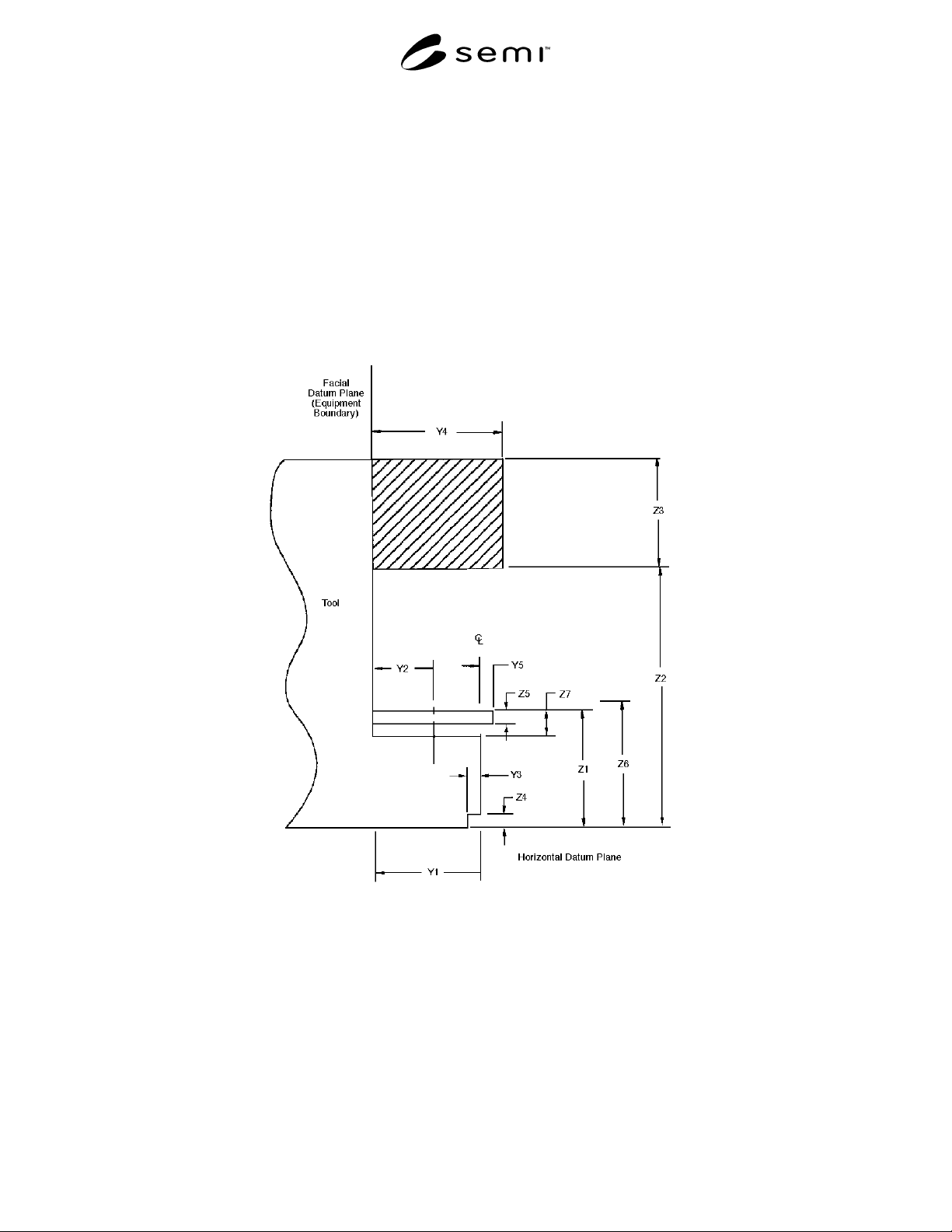
5.1.1 facial datum plane — the plane coincident with
the front face of the tool and perpendicular to the
horizontal and vertical datum planes.
5.1.2 horizontal datum plane — the plane coincident
with the top surface of the floor and perpendicular to
the facial datum plane of the tool.
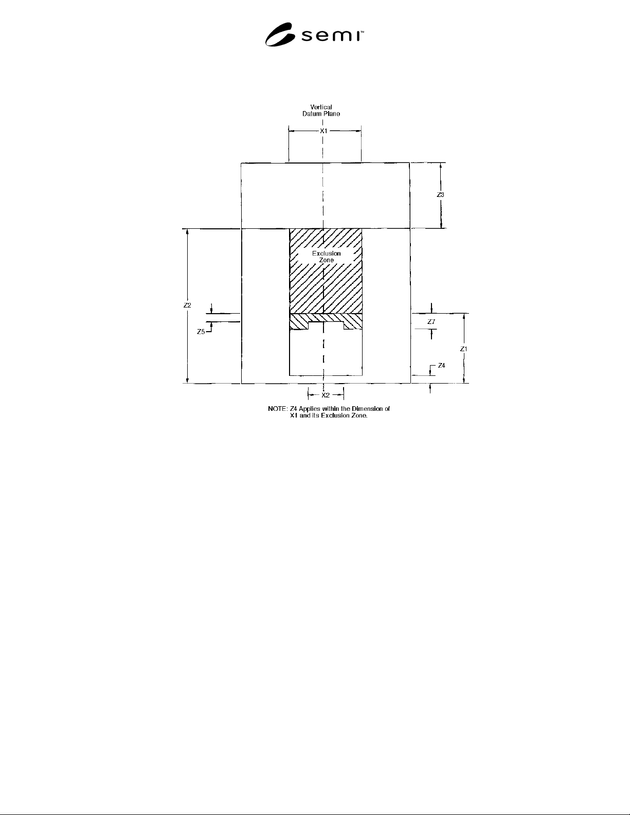
5.1.3 vertical datum plane — the plane that bisects the
tool port and is perpendicular to the horizontal and
facial datum planes.
5.2 Functional Description of Dimensions
5.2.1 X1 — width of exclusion zone reserved for
vertical material handling devices; maximum.
5.2.2 X2 — width of the tool port at Z7 below tool
load plane. This defines the horizontal limit of the tool
port in the x-y plane at that level, beyond which space
is reserved for transport equipment; maximum.
5.2.3 Y1 — maximum tool port protrusion from the
tool face. This dimension defines the limits of tool port
attachments.
5.2.4 Y2 — the centerline distance between substrate
and tool face when the substrate is delivered to the tool
port; ± 10 mm.
5.2.5 Y3 — depth of the exclusion zone used for PGV
cart alignment devices; maximum.
5.2.6 Y4 — overhead exclusion zone for ceiling-hung
material delivery systems; maximum.
5.2.7 Y5 — maximum protrusion from tool port. May
be used for mounting docking devices (mostly PGVs).
5.2.8 Z1 — height of tool port; ± 10 mm (load plane of
reference).
5.2.9 Z2 — the lowest point on an overhead delivery
system; minimum.
5.2.10 Z3 — the maximum volume height of an
overhead delivery system. This dimension extends the
full width of the tool.
SEMI D16-0998 © SEMI 1998 2
5.2.11 Z4 — the height of the exclusion zone used for PGV cart alignment devices.
5.2.12 Z5 — the maximum height of the protrusion used for docking devices.
5.2.13 Z6 — the location for the bottom plane of the first substrate. This dimension is not specified in this
document.
5.2.14 Z7 — height of exclusion zones used by conveyor rails and fork lifts; maximum.
6 Requirements
6.1 Dimensions and tolerances of the required features are specified in Table 1 and Figures 1A and 1B.
Figure 1A
Proposed Transport System to Tool Interface
SEMI D16-0998 © SEMI 19983
Figure 1B
Proposed Transport System to Tool Interface
6.2 Centerline location of the substrate, as it is delivered by the material handling equipment, with respect to the
tool face may not coincide with the centerline location of the substrate when the latter is finally positioned on the
tool port for substrate handling.
6.3 Substrate delivery is to be horizontal, active (pattern) face up.
6.4 The single substrate or carrier is to have a horizontal loading orientation with shorter side parallel to the tool
face plane.
6.5 Load height of the single substrate or carrier shall be adjustable on the material handling system within 20 (±
10) mm of the nominal height.
6.6 There should be no obstruction between the load port and the material delivery system within the defined
adjustable range of the load port height.
6.7 Load and unload mechanisms must allow operator-assisted loading. This implies clearance space for the
operator, as well as mechanisms that allow manual override.