semi合集-English.pdf - 第4494页
SEMI D19-0305 © SEMI 1999, 2005 1 SEMI D19-0305 TEST METHOD FOR THE DETERMINATION OF CHEMICAL RESISTANCE OF FLAT PANE L DISPLAY COLOR FILTERS This test method was technicall y approved by the Global Flat Panel Display Co…

SEMI D18-0299
E
© SEMI 1999, 2001 14
APPENDIX 1
NOTE: The material in this appendix is an official part of SEMI D18 and was approved by full letter ballot procedures on August
15, 1998.
A1-1 Application Notes
A1-1.1 The shape of the teeth holding the substrates is
not specified in this standard. The tooth surface that
touches the substrate should have a large radius to
minimize stress on the substrate and tooth.
A1-1.2 Extra clearance (larger than the pitch) has been
added below the bottom substrate (for non-random
sequential access to the substrates with a faster or less
precise robot). To increase the stability of Type A
Cassettes the points on the cassette bottom that are the
most distant from the lines connecting each pair of
coupling pins should be made as close as practical to
the horizontal datum plane so that the cassette cannot
tip very far off of the kinematic coupling.
NOTICE: These standards do not purport to address
safety issues, if any, associated with their use. It is the
responsibility of the user of these standards to establish
appropriate safety and health practices and determine
the applicability of regulatory limitations prior to use.
SEMI makes no warranties or representations as to the
suitability of the standards set forth herein for any
particular application. The determination of the
suitability of the standard is solely the responsibility of
the user. Users are cautioned to refer to manufacturer’s
instructions, product labels, product data sheets, and
other relevant literature respecting any materials
mentioned herein. These standards are subject to
change without notice.
The user’s attention is called to the possibility that
compliance with this standard may require use of
copyrighted material or of an invention covered by
patent rights. By publication of this standard, SEMI
takes no position respecting the validity of any patent
rights or copyrights asserted in connection with any
item mentioned in this standard. Users of this standard
are expressly advised that determination of any such
patent rights or copyrights, and the risk of infringement
of such rights, are entirely their own responsibility.
Copyright by SEMI® (Semiconductor Equipment and Materials
International), 3081 Zanker Road, San Jose, CA 95134. Reproduction o
f
the contents in whole or in part is forbidden without express written
consent of SEMI.

SEMI D19-0305 © SEMI 1999, 2005 1
SEMI D19-0305
TEST METHOD FOR THE DETERMINATION OF CHEMICAL
RESISTANCE OF FLAT PANEL DISPLAY COLOR FILTERS
This test method was technically approved by the Global Flat Panel Display Committee and is the direct
responsibility of the Japanese FPD Color Filter & Optical Elements Committee. Current edition approved by
the Japanese Regional Standards Committee on November 24, 2004. Initially available at www.semi.org
January 2005; to be published March 2005. Originally published in 1999; previously published in February
1999.
1 Purpose
1.1 This standard establishes two methods for evaluating the chemical resistance of FPD color filters. One of these
methods is qualitative, the other is quantitative.
2 Scope
2.1 These methods may be used by suppliers and users of color filters for FPD applications, for use in judging
quality of production and developing samples.
2.2 These methods test the chemical resistance of color filters by utilizing chemicals and conditions typically
employed in FPD manufacturing.
2.3 These methods are destructive.
NOTICE: This standard does not purport to address safety issues, if any, associated with its use. It is the
responsibility of the users of this standard to establish appropriate safety and health practices and determine the
applicability of regulatory or other limitations prior to use.
3 Limitations
3.1 This standard specifies only the methods for testing and evaluating chemical resistance of FPD color filters;
however, it does not specify the criteria against which the test results are compared.
3.2 This standard specifies only items for color filters, but not for flat panel displays incorporating color filters.
4 Referenced Documents
4.1 JIS Standards
1
(available in Japanese only)
JIS Z8113 — Glossary of Lighting Terms
JIS Z8120 — Glossary of Optical Terms
JIS Z8722 — Methods of Measurement of Color of Reflecting
JIS Z8730 — Method for Specification of Color Difference for Opaque Materials
4.2 Others
2
IEC Publication 50 (845) — International Electro-chemical Vocabulary (IEV)
NOTICE: Unless otherwise indicated, all documents cited shall be the latest published versions.
5 Terminology
5.1 Definitions
5.1.1 color illuminator — A light source having a uniform illumination plane which radiates diffuse light onto the
back surface of a sample to permit direct observation of the sample.
1 Japanese Standards Association, 4-1-24 Akasaka Minato-ku,Tokyo 107-8440 Japan, Telephone: +81-3-3583-8005, Fax: +81-3-3586-2014,
http://www.jsa.or.jp/
2 International Electrotechnical Commission, 3, rue de Varembé, Case Postale 131, CH-1211 Geneva 20, Switzerland. Telephone:
41.22.919.02.11; Fax: 41.22.919.03.00, www.iec.ch
SEMI D19-0305 © SEMI 1999, 2005 2
5.1.2 Definitions of additional terms used in this document may be found in JIS Z8113, JIS Z8122 and IEC
Publication 50 (845).
6 Summary of Method
6.1 A sample is placed in a suitable test container at controlled temperature for a specified period of time.
6.2 The sample is removed from the bath and residual chemicals removed.
6.3 The sample is examined visually for qualitative changes in appearance.
6.4 The sample is examined by microscope and/or surface profiler (stylus type) for material swelling.
6.5 The sample is measured per color layer for spectra transmittance.
6.6 The color difference for each color layer is calculated in one of two systems.
7 Apparatus
7.1 Test Container — A clean container shall be used with a sufficient size and depth to accommodate the sample
and appropriate chemicals. The container material must be chosen which will not be affected by tests executed under
this method. Note that chemicals should not change in quality by test container.
7.2 Instrumentation
7.2.1 Color Illuminator — This light source shall have chromaticity, color rendering, luminance and intensity
uniformity, diffusion, and a sufficient illumination area for observation of the samples to be measured.
7.2.2 Floodlight — This light shall have luminance uniformity and an illumination area sufficient for the samples to
be measured.
7.2.3 Microscope — The microscope used shall have appropriate magnification, normally 50
400.
7.2.4 Spectrophotometer — The spectrophotometer shall be in conformance with JIS Z8722 or an equivalent
standard.
7.2.5 Surface Profiler — The equipment which can measure the thickness with X-Y stage.
8 Reagents and Test Conditions
8.1 No specific requirements are described for the reagents. As long as the test conditions are reported with the test
result, any combination of chemical reagents with any condition can be used for the test. The test conditions should
reflect actual process conditions, which are specific for the selected FPD manufacturer. Some reagents suggested for
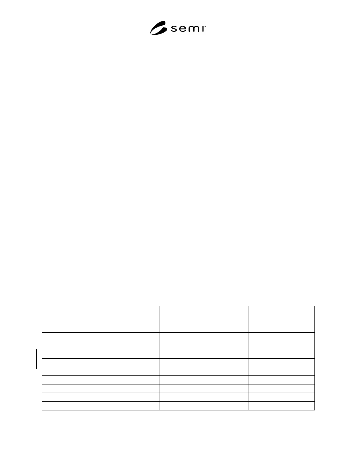
the test are given in Table 1.
Table 1 Chemicals Used for Chemical Resistance Tests and Related Conditions
Chemical
#1
Liquid Temperature (
o
C)
Soak Time
(minutes)
N-methyl-2 pyrolidone (NMP)
23 2
30
-butyrolactone 23 2
30
2-propanol (IPA)
23 2
30
propylene glycol monomethyl ether Acetate
23 2
30
ethylene glycol monobutyl ether
23 2
30
2.38% tetramethyl-ammoniumhydroxide (TMAH)
23 2
30
18% HCl
23 2
30
18% HCl
40 5
10
5% NaOH
23 2
10
5% KOH
23 2
10
#1
% = % by weight