semi合集-English.pdf - 第4504页
SEMI D22-1103 © SEMI 1999, 2003 2 Figure 1 6 Reference 6.1 Reference quantity of lig ht shall be measured with a substrate without object layer. 6.1.1 For exam ple, substrates described below ca n be adopted for refere n…
SEMI D22-1103 © SEMI 1999, 2003 1
SEMI D22-1103
TEST METHOD FOR THE DETERMINATION OF COLOR,
TRANSMITTANCE OF FPD COLOR FILTER ASSEMBLIES
This test method was technically approved by the Global Flat Panel Display Committee and is the direct
responsibility of the Japanese Flat Panel Display Committee. Current edition approved by the Japanese
Regional Standards Committee on August 8, 2003. Initially available at www.semi.org October 2003; to be
published November 2003. Originally published September 1999.
NOTICE: This document was completely rewritten in
2003.
1 Purpose
1.1 This standard establishes practices for measuring
selected characteristics of FPD color filters. These
methods are applicable to manufacturing, quality
control, and development operations.
2 Scope
2.1 This method is to be used by FPD color filter
suppliers and users to evaluate quality of products as
well as items under development.
2.2 This method shall be used in general to measure
the color characteristics and transmittance of FPD color
filter.
NOTICE: This standard does not purport to address
safety issues, if any, associated with its use. It is the
responsibility of the users of this standard to establish
appropriate safety and health practices and determine
the applicability of regulatory or other limitations prior
to use.
3 Referenced Standards
3.1 SEMI Standards
SEMI D13 — Terminology for FPD Color Filter
Assemblies
3.2 CIE Standards
1
CIE 1931 — Standard Colorimetric System
(Colorimetry – Official Recommendations of the CIE)
CIE 1976 (L*,a*,b*) — Color Space (Recommend-
ations on Uniform Color Spaces)
NOTICE: Unless otherwise indicated, all documents
cited shall be the latest published versions.
4 Summary of Method
4.1 Turn on the apparatus, and input measurement
parameters.
1 CIE International Commission on Illumination, Kegelgasse 27, A-
1030 Vienna, Austria
4.2 Warm up and stabilize the equipment.
4.3 Measure the reference quantity of light.
4.4 Set the sample on the measuring stage, and adjust
the point of measurement into the measuring spot.
4.5 Measure the sample quantity of light.
4.6 Print the results (color characteristics and
transmittance).
5 Apparatus
5.1 The measurement system shall have the following
specifications.
5.2 Wavelength range: variable between 380 and 780
mm, in increments of < 5nm.
5.3 Measuring area: Measuring spot size or the spot
size of incident beam on the sample surface is smaller
than the sub-pixel to be measured. (for example 2 to 50
micrometer in diameter).
5.4 Sample stage:
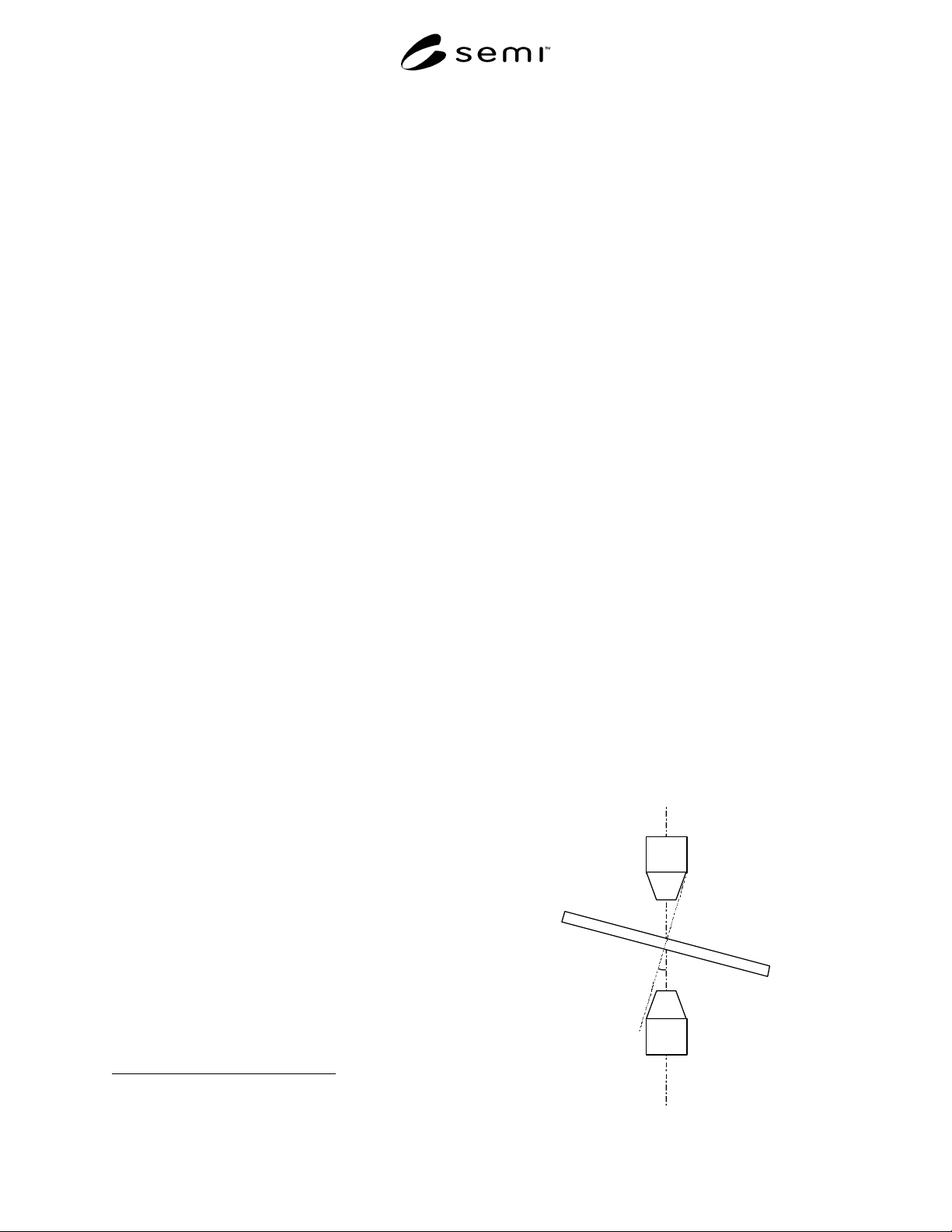
5.4.1 Sample surface can be set normal to the incident
beam. (See Figure 1)
5.4.2 The sample stage shall have a sufficient
mechanical travel to permit measurements within the
color filter area and in the transparent area of the
substrate outside the color filter material.
θ
Phot ometer
li
g
ht sour c
e
color filt er
Fi
g
ure 1

SEMI D22-1103 © SEMI 1999, 2003 2
Figure 1
6 Reference
6.1 Reference quantity of light shall be measured with
a substrate without object layer.
6.1.1 For example, substrates described below can be
adopted for reference.
Ex. A glass substrate for color filter
A glass substrate out of the color filter area
6.1.2 As for the definition of glass substrate, refer to
D13.
7 Calibration
7.1 Calibrate the apparatus in accordance with
manufacture' s instructions.
7.2 Record characteristics of the instrument observed
during this calibration, e.g., linearity, wavelength shift,
etc.
8 Procedure
8.1 Turn on the apparatus and input the measurement
condition parameters.
Condition Wavelength range
Spot size
Gain, Integration time etc.
8.2 Before operation, warm up and stabilize the
equipment for a specified period of time (according to
the instruction manual of the apparatus).
8.3 Measure the reference data (dark quantity of light,
reference quantity of light)
8.4 Set the sample onto the stage and adjust the sample
to the measuring position.
8.5 Measure quantity of light of the sample.
8.6 Record the data.
9 Reporting Results
9.1 The report must contain the following items:
9.1.1 Date of the measurement and operator ID
9.1.2 Manufacturer, model, series of the apparatus, and
the version of the software installed.
9.1.3 Reference material.
9.1.4 Measuring conditions (Wavelength range, Spot
size)
9.1.5 An illustration of the measured points in the
sample.
9.1.6 Color characteristics measurement;
9.1.6.1 Color characteristics
9.1.6.2 Graph
*Refer to the following standard
CIE 1931-x,y
CIE 1976-(L*,a*,b*) or (L*,u*,v*)
9.1.7 Transmittance
9.1.7.1 Graph
Wavelength(X-axis) vs.
Transmittance(Y-axis)
10 Correction Between Different Apparatus
10.1 To compare the data of different apparatus, you
should take care about the apparatus difference.
10.2 To avoid the confusion, exchanging some
common test pieces, and comparing of the measured
data are recommended.
11 Related Documents
11.1 ASTM Standards
2
E179-96 — Standard Guide for Selection of Geometric
Conditions for Measurement of Reflection and
Transmission Properties of Materials.
E1164-02 — Standard Practice for Obtaining
Spectrophotometric Data for Object-Color Evaluation.
E1345-98 — Standard Practice for Reducing the Effect
of Variability of Color Measurement by Use of
Multiple Measurements.
NOTICE: SEMI makes no warranties or
representations as to the suitability of the standards set
forth herein for any particular application. The
determination of the suitability of the standard is solely
the responsibility of the user. Users are cautioned to
refer to manufacturer' s instructions, product labels,
product data sheets, and other relevant literature,
respecting any materials or equipment mentioned
herein. These standards are subject to change without
notice.
By publication of this standard, Semiconductor
Equipment and Materials International (SEMI) takes no
position respecting the validity of any patent rights or
copyrights asserted in connection with any items
mentioned in this standard. Users of this standard are
expressly advised that determination of any such patent
rights or copyrights, and the risk of infringement of
such rights are entirely their own responsibility.
2 American Society for Testing and Materials, 100 Barr Harbor
Drive, West Conshohocken, Pennsylvania 19428-2959, USA.
Telephone: 610.832.9585, Fax: 610.832.9555, Website:
www.astm.org

SEMI D23-0999 © SEMI 19991
SEMI D23-0999
GUIDE FOR COST OF EQUIPMENT OWNERSHIP (CEO)
CALCULATION FOR FPD EQUIPMENT
This guide was technically approved by the Global Flat Panel Display Equipment Committee and is the direct
responsibility of the Japanese Flat Panel Display Equipment Committee. Current edition approved by the
Japanese Regional Standards Committee on June 1, 1999. Initially available on SEMI OnLine August 1999;
to be published September 1999.
1 Purpose
1.1 The purpose of this document is to provide a
standard, simple CEO calculation method for
evaluating FPD manufacturing equipment. With this
document, the following merits can be expected:
1.1.1 Both panel and equipment manuf acturers, as
well as material manufacturers can work from the same
standard with regard to cost.
1.1.2 Panel manufacturers’ basis for equipment
comparison will become clear, which will, in turn, help
in equipment selection.
1.1.3 The document will serve to clarify cost reduction
items as well as benchmark cost reduction activities.
1.1.4 Direction for improvement for equipment
manufacturers will become clear.
1.1.5 By doing a separate analysis, comparison, and
evaluation of lines, equipment for different substrate
sizes will become simpler.
2 Scope
2.1 This standard focuses on each equipment in the
FPD production line. It is used to define the calculation
method for cost of installing/operating that equipment,
to define the calculation method for productivity of that
equipment, and to quantify CEO of that equipment.
2.2 It is necessary to clarify the substrate sizes that can
be handled by this equipment. However, this standard
does not deal with the equipment process performance.
It takes the point of view that each panel manufacturer
should evaluate each equipment’s process performance,
including yield, based on their own process
requirements.
2.3 This standard does not purport to address all of the
safety issues associated with its use. It is the
responsibility of the users of this standard to establish
appropriate safety and health practices and determine
the applicablity of regulatory limitations prior to use.
3 Limitations
3.1 This standard does not attempt to include all
elements necessary for equipment evaluation, and may
be seen as incomplete from certain perspectives.
However, it is believed that it will serve as the
foundation for comparative evaluations.
4 Referenced Standards
None.
5 Terminology
5.1 Definitions for each of the items are listed in the
following table.