semi合集-English.pdf - 第4515页
SEMI D24-0200 © SEM I 2000 5 Warp Detecte d along edge by fee ler gauge (Back S urface Un constrained) X Z 0 Figure 3 Warp Rounded bevel 0.1 - 0.6 mm Figure 4 Edge Cond ition
SEMI D24-0200 © SEMI 2000 4
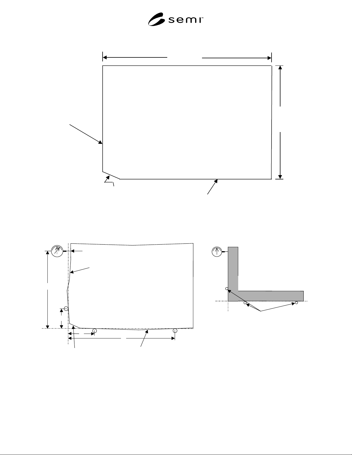
(Pattern Surface)
Length (L)
Width (W)
Short Reference
Edge (SRE)
Orientation Corner
Long Reference Edge (LRE)
Figure 1
Reference Items
(Pattern Surface)
Short Reference Edge (SRE)
1 Orientation Corner
Long Reference Edge (LRE)
Dial
Gauge
Pr
a
b
c
d
Calibration using Square
Gauge
Dial
Gauge
Zero
Support pins
NOTE: a, b, c, and d are defined between supplier and customer.
Figure 2
Squareness
SEMI D24-0200 © SEMI 20005
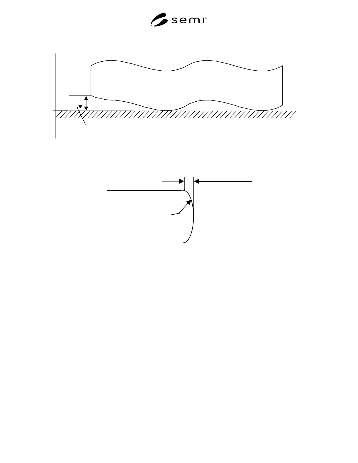
Warp
Detected along edge by feeler gauge
(Back Surface Unconstrained)
X
Z
0
Figure 3
Warp
Rounded bevel
0.1 - 0.6 mm
Figure 4
Edge Condition
SEMI D24-0200 © SEMI 2000 6
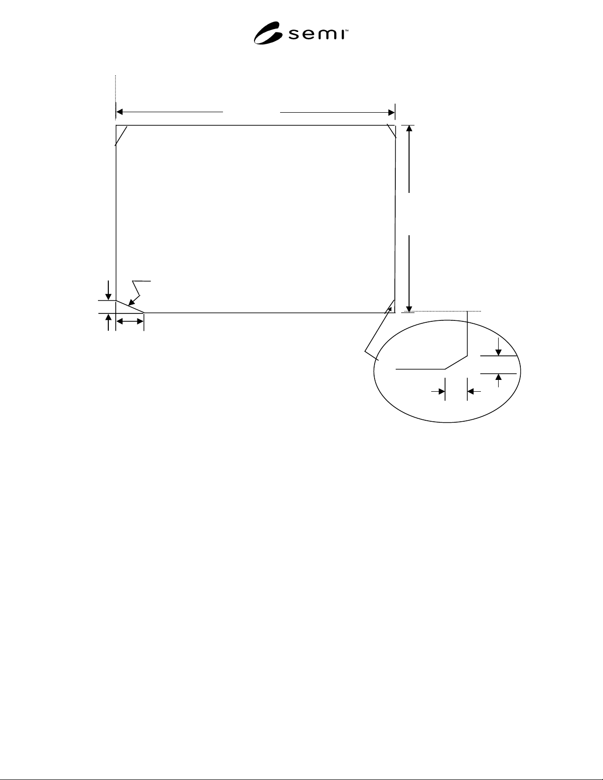
C
2x
(Pattern Surface)
Length(L)
Width(W)
Orientation
(LRE)
(SRE)
Corner Cut
(3 places)
Y-Axis
X-Axis
C1x
C1y
C2x
C2y
Figure 5
Orientation Corner and Corner Cuts