semi合集-English.pdf - 第455页
SEMI E66-1103 © SEMI 1997, 2003 4 cone between 6.35 m m and 12.7 mm (1/4 in. and 1/2 in.) face-seal connect ions. Figure 3 Isokinetic Sampler Design Table 1 Maximum IKS Inlet Flow (liters/min.) ID Probe D 2 (note)mm (inc…
SEMI E66-1103 © SEMI 1997, 2003 3
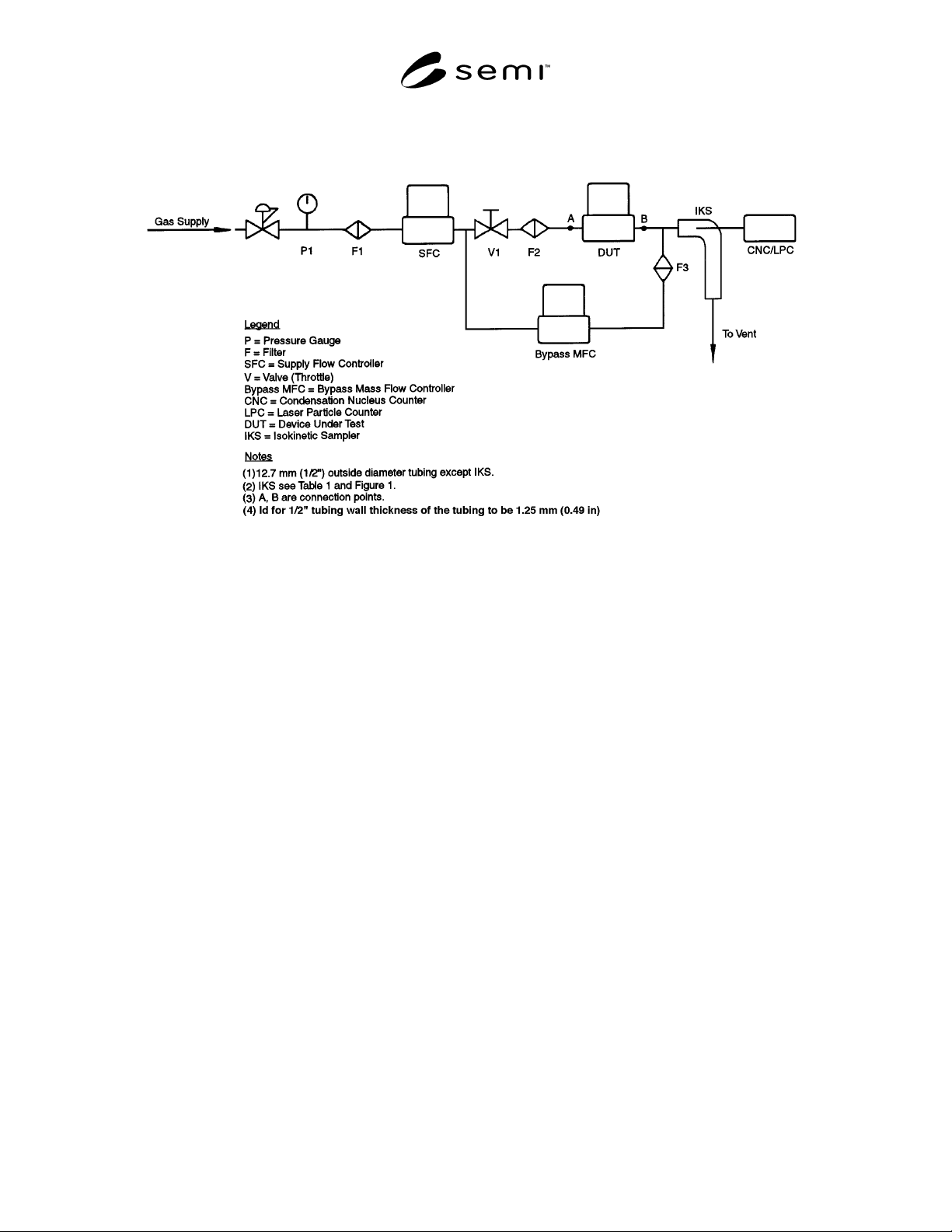
Figure 1
Test Set-Up when Test Flow < Sample Flow
Figure 2
Test Set-Up when Test Flow > Sample Flow
6 Summary of Test Method
6.1 Background count is determined for steady state
control, dynamic control, and impact tests. The steady
state control mode test, dynamic control mode test, and
impact test are run by counting particles for the time
necessary to achieve a stable particle level. Background
testing is performed again.
7 Significance and Use
7.1 The significance of this test method is that it
defines a procedure for testing mass flow controllers
intended for installation into a high-purity gas system.
It is intended for use by manufacturers and end users.
8 Apparatus
8.1 Test Gas — Nitrogen of minimum dryness, with -
40°C (-40°F) dew point at 790.57 kPa (100 psig) and
with < 10 ppm of total hydrocarbons.
8.2 Membrane Filters — To provide filtered test gas,
nine-log retentive to larger than 0.01 mm particles, with
a pressure drop of less than 7.91 kPa (1 psid) at 283,170
sccm (10 scfm) for a 790.57 kPa (100 psig) inlet, and
capable of achieving less than one particle
3
0.01 mm
per cubic foot of test gas under test conditions.
8.3 Pressure Regulator — Made of electropolished
316L stainless steel, with an internal surface finish of
0.18 mm (7 µin.) R
a
and 0.25 mm (10 µin.) Rmax, to
maintain system test pressure.
8.4 Pressure Gauge or Transducer — Made of
electropolished 316L stainless steel, with an internal
surface finish of 0.18 mm (7 µin.) R
a
and 0.25 mm (10
µin.) Rmax, to monitor system test pressure.
8.5 Throttle Valve — Made of electropolished 316L
stainless steel, with an internal surface finish of 0.18
mm (7 µin.) R
a
and 0.25 mm (10 µin.) Rmax, to
proportion flow in test system.
8.6 Tubing — Made of electropolished 316L stainless
steel, with an internal surface finish of 0.18 mm (7 µin.)
Ra and 0.25 mm (10 µin.) Rmax.
8.7 Supply Flow Controller (SFC) — Metal-sealed,
used to establish a flow rate through the spool piece in
the absence of the DUT, with a settling time less than or
equal to that of the DUT. More than one range SFC
may be required to run all the tests.
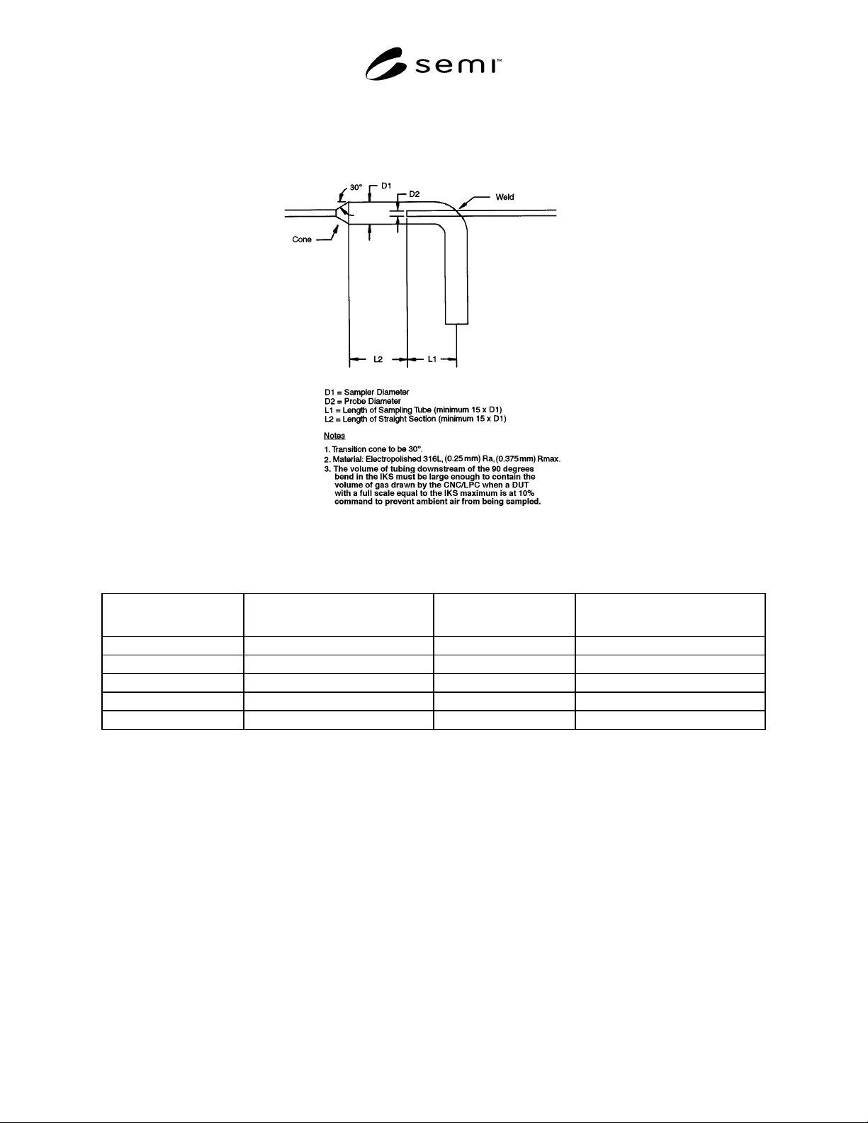
8.8 Sampler — Constructed according to the drawing
and design parameters shown in Figure 3 and Table 1,
to collect gas from the stream exiting the test device,
where the sample is near-isokinetic in design.
8.9 Upstream Adapter — To connect 12.7 mm (1/2 in.)
tubing to the test device. For 12.7 mm (1/2 in.) test
devices, the adapter is a simple face-seal connector. For
6.35 mm (1/4 in.) test devices, the adapter is a tapered
SEMI E66-1103 © SEMI 1997, 2003 4
cone between 6.35 mm and 12.7 mm (1/4 in. and 1/2 in.) face-seal connections.
Figure 3
Isokinetic Sampler Design
Table 1
Maximum IKS Inlet Flow
(liters/min.)
ID Probe D
2
(note)mm (inches)
ID Sampler D
1
- mm
(inches)
Worst-Case Dilution
300 4.62 (0.180) 68.58 (2.700) 3:1
100 4.62 (0.180) 39.62 (1.560) 3:1
30 4.62 (0.180) 21.44 (0.844) 3:1
10 4.62 (0.180) 11.99 (0.472) 3:1
3 7.75 (0.305) 12.57 (0.495) 2:1
NOTE 1: For 300,000 to 10,000 cc/min. test flow:
• Constant sample velocity = 132 cm/sec.
• D2 = 4.57 mm (0.180 in.) ID standard 6.35 mm (1/4 in.) tubing (see Figure 3)
• For 1.41 l/min. CNC
NOTE 2: For 3,000 cc/min. test flow:
• Constant sample velocity = 49.9 cm/sec.
• D
2
= 7.75 mm (0.305 in.) ID standard 9.53 mm (3/8 in.) tubing (see Figure 3)
• For 1.41 l/min. CNC
8.10 Downstream Adapter — To connect 12.7 mm (1/2 in.) sampler tubing to the test device. For 12.7 mm (1/2 in.)
test devices, the adapter is a simple face-seal connector. For 6.35 mm (1/4 in.) test devices, the adapter is a tapered
cone between 6.35 mm and 12.7 mm (1/4 in. and 1/2 in.) face-seal connections.
8.11 Spool Pieces — Of the same inside diameter as the inside diameter fittings on the test piece and of a length
representative of the DUT, to be installed in the system in place of the test device while obtaining background
counts for the system.
SEMI E66-1103 © SEMI 1997, 2003 5
8.12 Fittings — Face seal connectors or compression fittings, depending on test component end connections. The
end connection fittings of each DUT being compared must be of the same type.
8.13 Metal Gaskets — New gaskets should be used for each new connection.
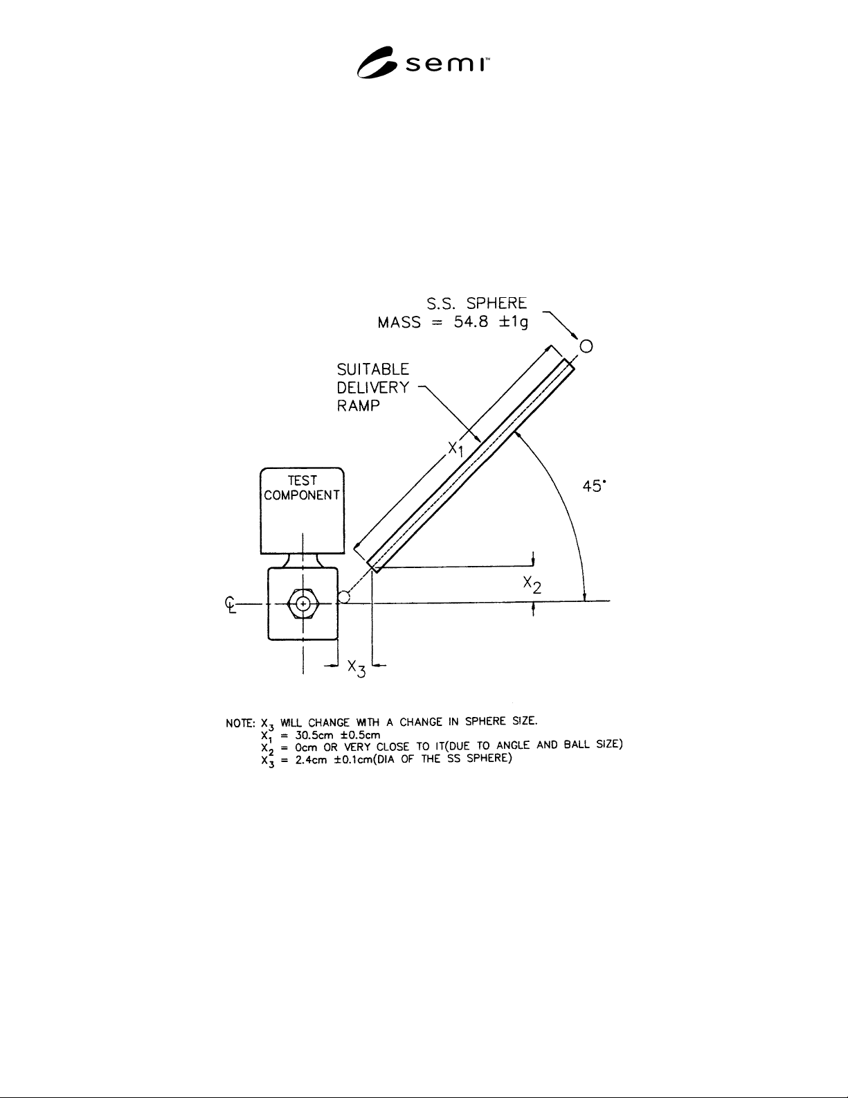
8.14 Mechanical Shock Device — To provide mechanical shock by impact to the test device. (See Figure 4.)
8.15 Instrumentation — Condensation nucleus counter (CNC) or laser particle counter (LPC) to collect particle
count data.
8.16 Isokinetic Sampler (IKS) — A static device used to collect a representative sample that is not influenced by
flow characteristics and/or particle size (see Figure 3). Other designs of isokinetic samplers are permitted as long as
they collect a representative sample of the flow.
Figure 4
Mechanical Shock Test Device
NOTE: Position the delivery ramp so that the position of impact is at the midpoint of the axial centerline of the device under test.
9 Sampling, Test Specimens, and Test Units
9.1 MFCs regulate flows greater than or less than the flow requirements of particle counters; therefore, two
different sampling techniques have been defined, isokinetic sampling and direct sampling.
9.1.1 Direct Sampling — The direct sampling method is used when the test flow is less than or equal to the sample
flow. (See Figure 1.)
9.1.1.1 In this case, gas exiting the DUT is introduced directly into the CNC. A tee, equipped with a filtered branch,
is inserted between the DUT and the CNC to provide make-up flow to the CNC. The volume and overall length of
the tubing connecting the DUT to the tee assembly should be minimized.