semi合集-English.pdf - 第4590页
SEMI D35-1103 E © SEMI 2003 2 5.7 Measure t he lamp voltage when t he rated lamp current is stable. 5.8 Measure t he luminance and chromaticity when the rated lamp current is stable. 5.9 Turn off t he CCFL and remove it …
SEMI D35-1103
E
© SEMI 2003 1
SEMI D35-1103
E
TEST METHOD FOR MEASUREMENT OF COLD CATHODE
FLUORESCENT LAMP (CCFL) CHARACTERISTICS
This test method was technically approved by the Global Flat Panel Display Committee and is the direct
responsibility of the Japanese Flat Panel Display Committee. Current edition approved by the Japanese
Regional Standards Committee on August 8, 2003. Initially available at www.semi.org October 2003; to be
published November 2003.
E
This standard was editorially modified in November 2004 to correct editorial errors. Changes were made to
multiple sections, figures, and tables.
1 Purpose
1.1 The purpose of this document is to standardize the
method for measurement of electrical and optical
characteristics of cold cathode fluorescent lamp
(CCFL).
2 Scope
2.1 This method is to be used by CCFL suppliers and
users to evaluate quality of products as well as items
under development.
2.2 This method shall be used in general for CCFL to
measure the initial characteristics of CCFL (single
item) and its reliability after tests, and to carry out
quality inspection for incoming and outgoing CCFLs.
NOTICE: This standard does not purport to address
safety issues, if any, associated with its use. It is the
responsibility of the users of this standard to establish
appropriate safety and health practices and determine
the applicability of regulatory or other limitations prior
to use.
3 Referenced Standards
3.1 JIS Standards
1
JIS Z 8113 — Lighting vocabulary
3.2 IEC Standards
2
IEC 60050 (845) — Lighting, Section 1: Radiation,
Quantities and Units, 3: Colorimetry
NOTICE: Unless otherwise indicated, all documents
cited shall be the latest published versions.
1 Japanese Standards Association, 1-24, Akasaka 4 Chome, Minato-
Ku, Tokyo, 107-8840 Japan. Tel: +81-3-3583-8000, E-mail:
webmaster@jsa.or.jp, http://www.jsa.or.jp
2 International Electrotechnical Commision(IEC), 3, rue de
Varembé , P.O. Box131 CH-1211 Geneva 20, Switzerland. Tel: +41-
22-919-02-11, E-mail: iec@iec.ch, http://www.iec.ch
4 Terminology
4.1 Abbreviations and Acronyms
4.1.1 CCFL — Cold Cathode Fluorescent Lamp
4.2 Definitions
4.2.1 effective emission area — an area (length) in
which a certain percentage of luminance against the
luminance of a central part is maintained with almost
even luminance distribution (LE[mm]).
4.2.2 lamp current — effective current inside the lamp
(IL[mArms]). (The GND side shall be measured.)
4.2.3 lamp voltage — effective voltage across both
ends (between two electrodes) of a lamp at rated lamp
current (VL[Vrms]).
4.2.4 lamp wattage — a product of the lamp current,
lamp voltage and a power factor. A reference value
(W[Wrms]).
4.2.5 luminance stabilization time — the time to reach
a certain percentage of the luminance of a central part
(Ts[min.]).
4.2.6 stable discharge voltage — effective voltage at
lamp ends (between two electrodes) when a main
discharge starts (Es[Vrms]).
5 Summary of Method
5.1 Warm up the measuring equipment for a specified
period of time to stabilize (according to the instruction
manual of measuring equipment).
5.2 Keep the lamp wall temperature of a CCFL and the
ambient temperature in equilibrium. The ambient
temperature shall be stable.
5.3 Set the CCFL on the measuring equipment.
5.4 Adjust the point of measurement (viewing angle),
focus and distance.
5.5 Measure the stable discharge voltage.
5.6 Turn on the CCFL by applying a rated current and
measure the lamp current when it is stable.
SEMI D35-1103
E
© SEMI 2003 2
5.7 Measure the lamp voltage when the rated lamp
current is stable.
5.8 Measure the luminance and chromaticity when the
rated lamp current is stable.
5.9 Turn off the CCFL and remove it from the
measuring equipment.
5.10 Refer to Sections 9.3 and 9.4 regarding the
measurement of the effective emission area and
luminance stabilization time.
6 Apparatus
6.1 Electrical Apparatus — Choose measuring
equipment to use from the following devices and
specify which devices were used, and also specify a
measuring circuit, lighting frequency, rating of
electrical wire and its length in the report. The
electrical (and optical) characteristics of CCFL depend
on the frequency of the lighting circuit.
6.1.1 Power Supply — For the lighting of CCFL, use a
power supply unit that provides the substantial
sinusoidal waveform and frequency of 50–60 kHz.
Also, use the combination of a Stabilized DC power
supply unit and an inverter, or a power supply unit
designed specially as an integrated type (special
purpose). The output voltage of either of them is
variable but the variability shall not affect the
measurement.
6.1.2 Meter — Use a meter that indicates true AC
voltage values for measurement. The meter built in a
special purpose power supply unit shall indicate true
values as well.
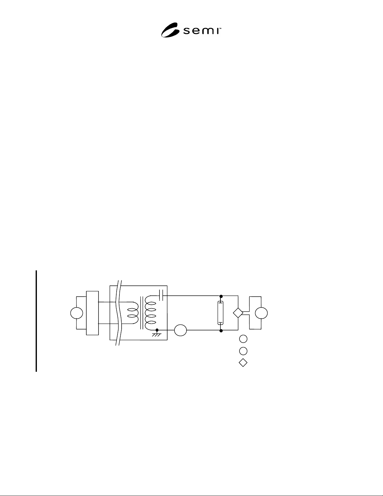
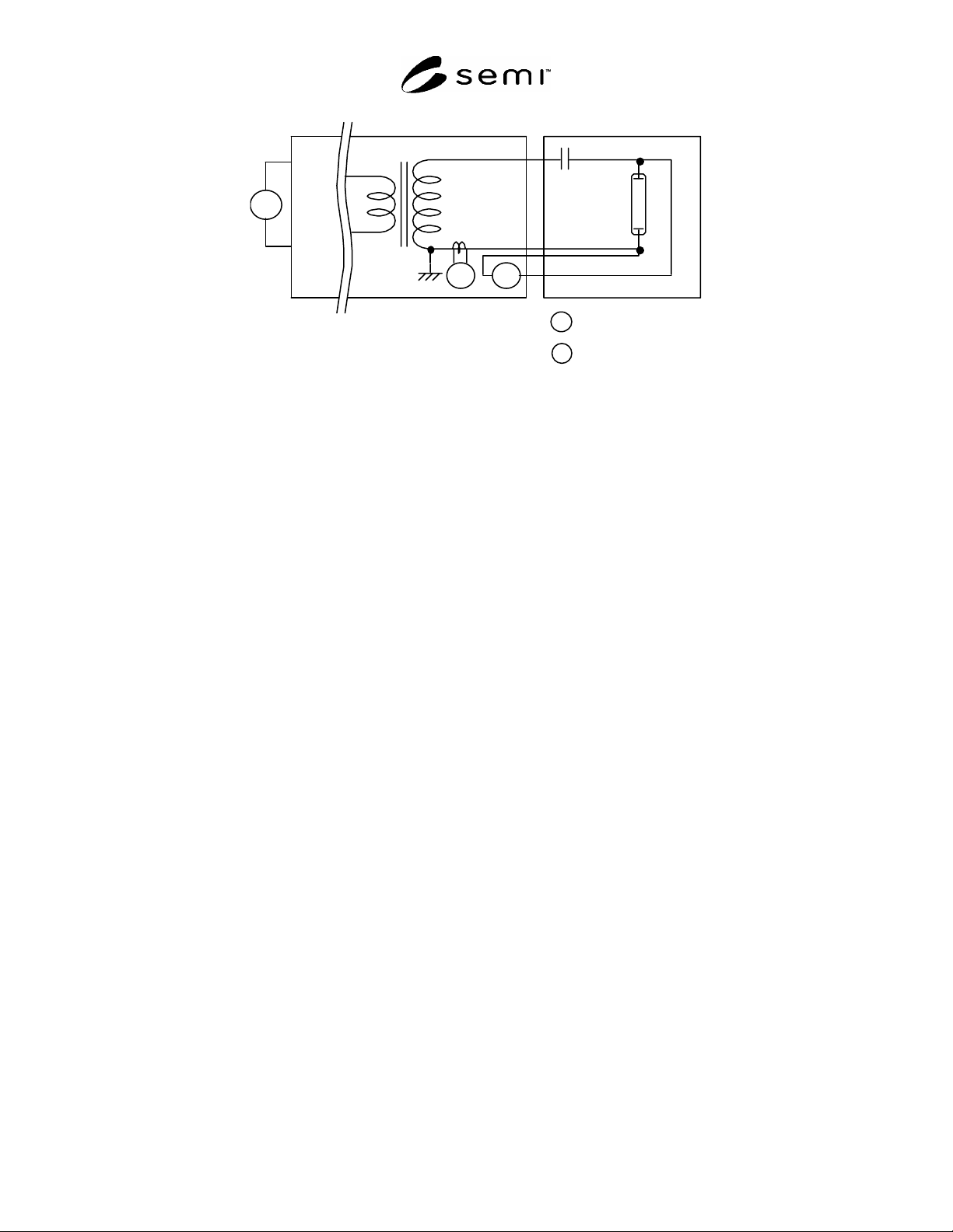
6.1.3 Circuit — The circuit to measure electrical
characteristics shall conform to Figure 1 or Figure 2.
6.1.4 Specify the ratings and lengths of electrical wires
that connect each meter and lamp. Since the wires
produce leakage current due to stray capacitance and
the amount differs according to the lengths, set the
wires as short as possible and do not bundle them.
6.2 Optical Measuring Equipment — Choose a
measuring equipment to use from the following devices
and specify which devices were used, and also specify
the measuring distance, viewing angle, and ambient
temperature in the report. The optical (and electrical)
characteristics of CCFL depend on the ambient (lamp
wall) temperature.
6.2.1 Black Box for Measurement — The black box
used to measure shall be so designed that the lamp
surface may not be affected by wind. The delustered
black paint shall be applied on the inside of the box so
that it may not be affected by the background color or
reflected light when the luminance is measured. In
addition, in order not to be affected by stray
capacitance, non-conductive materials shall be used.
For the installation of a CCFL in the box, a fixing
method shall be employed for avoiding the impact to
the lamp wall temperature distribution at lighting.
mA
+
GND
±
Inverter
mA
CCFL
V
mA
V
Themocouple ammeter
True value voltmeter
High-voltage prove
Figure 1
Combination of Stabilized DC Power Source and Inverter
SEMI D35-1103
E
© SEMI 2003 3
mA
~
V
~
CCFL
Exclusive power supply
12pF
mA
~
V
~
Themocouple ammeter
True value voltmeter
Figure 2
Exclusive Power Supply
6.2.2 Meter — Use a spectroradiometer or colorimeter
to measure the luminance and chromaticity. Keep the
spectroradiometer under control of calibration system
with the meter of national standard and traceability.
Calibrate the colorimeter in such a way that it can
reproduce the luminance value of a master CCFL
obtained by a calibrated spectroradiometer. Since each
colorimeter has the instrumental error and changes with
the passage of time, the calibration is necessary for
daily use. For the calibration, a master CCFL, which
has the emission spectrum value close to that of a
CCFL to be measured, shall be used.
6.2.3 Diagram for Measurement — The diagram for
optical measurement shall conform to Figure 3.
7 Measurement Conditions
7.1 The place for measurement shall be kept at
25 ± 2°C for ambient temperature and 30–85%RH. The
temperature fluctuation shall be within 1°C and if the
temperature is specified, the measurement shall be
carried out at such temperature. There shall be no wind
or vibration that may affect the measurement.
7.2 For the measurement of luminance and
chromaticity, arrange the situation where ambient
reflected light may not affect it or such can be ignored.
7.3 For the measurement of voltage, points to be
measured shall be specified in circuit diagrams.
Measured values may vary by the impact of ballast
capacitor or probe based upon whether the points
measured are located at an inverter transformer side or
a lamp side (or located at front or rear side of ballast
capacitor).
7.4 The electrostatic capacity of a high voltage probe
used to measure a voltage shall be so small that the
impact to the probe by leakage current may be less and
it shall be specified.
8 Test Specimen
8.1 Use a CCFL in which the wall temperature and
ambient temperature are kept in equilibrium before
lighting. Especially when measuring the stable
discharge voltage again after the first measurement,
carry out after the lamp has been in equilibrium on both
temperatures, the lamp wall temperature and ambient
temperature.
8.2 Fix a CCFL horizontally along its long side on the
jig of the above-mentioned equipment and this method
shall not affect the temperature distribution on the wall.
The measured point shall be measured in the air.