semi合集-English.pdf - 第4592页
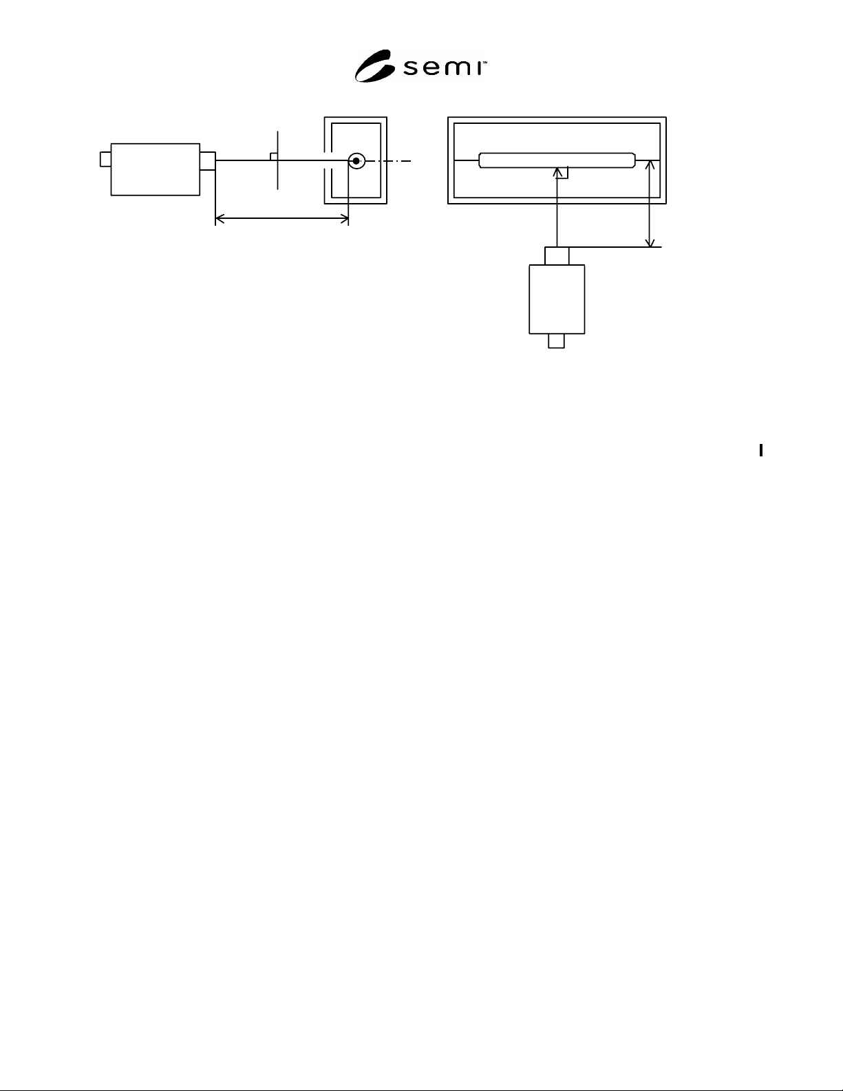
SEMI D35-1103 E © SEMI 2003 4 Distance of measurement W i ndle s s s t a t e Spectro ra di o m eter or Colorime t er Di s ta n ce o f m eas u rem en t CCF L Spectro ra di o m eter or Color ime te r Figure 3 Optical Chara…
SEMI D35-1103
E
© SEMI 2003 3
mA
~
V
~
CCFL
Exclusive power supply
12pF
mA
~
V
~
Themocouple ammeter
True value voltmeter
Figure 2
Exclusive Power Supply
6.2.2 Meter — Use a spectroradiometer or colorimeter
to measure the luminance and chromaticity. Keep the
spectroradiometer under control of calibration system
with the meter of national standard and traceability.
Calibrate the colorimeter in such a way that it can
reproduce the luminance value of a master CCFL
obtained by a calibrated spectroradiometer. Since each
colorimeter has the instrumental error and changes with
the passage of time, the calibration is necessary for
daily use. For the calibration, a master CCFL, which
has the emission spectrum value close to that of a
CCFL to be measured, shall be used.
6.2.3 Diagram for Measurement — The diagram for
optical measurement shall conform to Figure 3.
7 Measurement Conditions
7.1 The place for measurement shall be kept at
25 ± 2°C for ambient temperature and 30–85%RH. The
temperature fluctuation shall be within 1°C and if the
temperature is specified, the measurement shall be
carried out at such temperature. There shall be no wind
or vibration that may affect the measurement.
7.2 For the measurement of luminance and
chromaticity, arrange the situation where ambient
reflected light may not affect it or such can be ignored.
7.3 For the measurement of voltage, points to be
measured shall be specified in circuit diagrams.
Measured values may vary by the impact of ballast
capacitor or probe based upon whether the points
measured are located at an inverter transformer side or
a lamp side (or located at front or rear side of ballast
capacitor).
7.4 The electrostatic capacity of a high voltage probe
used to measure a voltage shall be so small that the
impact to the probe by leakage current may be less and
it shall be specified.
8 Test Specimen
8.1 Use a CCFL in which the wall temperature and
ambient temperature are kept in equilibrium before
lighting. Especially when measuring the stable
discharge voltage again after the first measurement,
carry out after the lamp has been in equilibrium on both
temperatures, the lamp wall temperature and ambient
temperature.
8.2 Fix a CCFL horizontally along its long side on the
jig of the above-mentioned equipment and this method
shall not affect the temperature distribution on the wall.
The measured point shall be measured in the air.
SEMI D35-1103
E
© SEMI 2003 4
Distance of
measurement
Windle ss stat e
Spectroradiometer
or Colorimeter
Distance of measurement
CCFL
Spectroradiometer
or Colorimeter
Figure 3
Optical Characteristics Measurement
9 Procedure
9.1 Measurement of Electrical Characteristics
9.1.1 Measurement of Stable Discharge Voltage —
Apply zero or very low voltage to the both ends of a
lamp (between two electrodes) and increase the voltage
gradually (slide-up). The lamp starts to discharge after
the voltage reaches a certain value. Furthermore,
increase the voltage gradually (slide-up) and measure
the potential difference between the lamp ends
(electrodes) as a stable discharge voltage when a main
discharge starts.
9.1.2 Measurement of Lamp Current — Adjust the
output voltage of power supply unit to gain a specified
lamp current. Measure the lamp current at GND
terminal when it becomes stable at a specified value.
Record the preset voltage of the power supply as well.
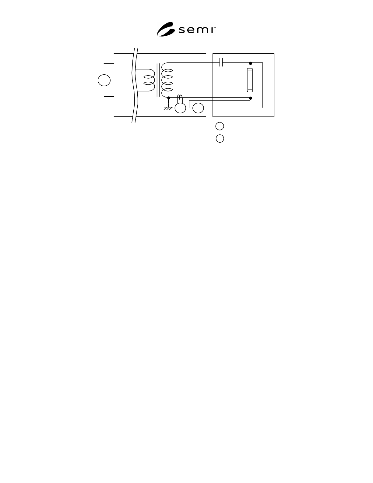
(Refer to Figure 1 or Figure 2.)
9.1.3 Measurement of Lamp Voltage — Measure the
potential difference between both ends (electrodes) of a
lamp as a lamp voltage when the lamp current becomes
stable at a specified lamp current. If the lamp current is
affected when a probe is connected, adjust the lamp
current to make it a specified lamp current. Measure
the lamp current after it becomes stable.
9.1.4 Lamp Wattage — It is defined as a product of
lamp current, lamp voltage and power factor
(W = VL × IL × cos) and expressed as a reference
value. When the phase difference between the lamp
current and lamp voltage can be ignored and if such
situation is specified, the product of the lamp current
and lamp voltage (W = VL × IL) may be expressed as a
reference value.
9.2 Measurement of Optical Characteristics
9.2.1 Point of Measurement — The point is the side
surface of a lamp, which is within the range of viewing
angle (black circle) of a measuring instrument. The area
of measurement is the central part of the lamp. The
point of measurement shall be so small relatively to the
inner diameter of the lamp that the dislocation of the
point may not vary the luminance and chromaticity.
The point of measurement is a cylindrical surface but it
could be regarded as a plain surface due to the
smallness. (See Figure 5.) The dispersion due to
dislocation of a point of measurement is smaller within
the range that is less than or equal to 50% of the inner
diameter. The luminance decreases in the other range.
9.2.2 Distance of Measurement — The distance shall
be from a lamp surface to be measured to a light-
receiving lens surface of a measuring instrument. The
size of viewing angle varies according to adjustment by
luminance meter and the distance of measurement, set
the distance to match the inner diameter mentioned
above. When measuring, the inner surface of the lamp
and the focal point shall be well matched (Figure 5). (If
the focal point of the luminance meter is displaced, the
luminance and chromaticity values will not be indicated
correctly.)
9.2.3 Timing of Measurement — Measure after the
luminance seems stable at a specified lamp current
(where the luminance fluctuation difference is within
± 3% of the stable luminance, for example). (See Figure
4.)

SEMI D35-1103
E
© SEMI 2003 5
Me asure me nt St arte d
±3%
Overcurrent
Luminanc e
100%
0
S
Figure 4
Measuring Time of Optical Characteristics
Commentary on Figure 4: The CCFL luminance has a special rising property. The highest luminance and stable
luminance vary by the combination of ambient temperature and lamp current and the transitions vary as well. This is
based upon the fact that the CCFL luminance depends on temperature and the generated heat by lighting affects it.
For this reason, the luminance varies until the lamp wall temperature becomes stable. Before the measurement, grasp
the special rising property of luminance and set the timing of measurement of the stable luminance.
9.2.4 Measurement of Luminance — Set a spectroradiometer or a colorimeter vertical to a side to be measured and
measure according to the above-mentioned instruction of measurement. Avoid shades of mercury particles in the
lamp. (See Figure 5.)
Station Diame
t
Lamp insi
d
diamete
Lamp outsi
d
diamete
M ercury Grain
(Within 50%
inner diame
t
Station Diameter
(Within 50% of
inner diameter)
Lamp inner
diameter
Lamp outer
diameter
Figure 5
Measuring Spot (Diameter) for Optical Characteristics
9.2.5 Measurement of Chromaticity — Measure in the same manner and at the same time of the measurement of
luminance.
9.3 Measurement of Effective Length of Luminous Part — Measure when the luminance is fully stable at a specified
lamp current according to the measuring conditions mentioned above. The luminance varies greatly around
electrodes since the temperature variation is big among points of measurement due to high temperature of a lamp
wall. Sufficient aging shall be performed before measurement to avoid impacts of the change of passage of time to