semi合集-English.pdf - 第4639页
SEMI C3.2-030 1 © SEMI 1981, 2001 3 4.4.2 Instrument Para meters 4.4.2.1 C olumn: Porapak QS 3.5 m (1 2 ft ) by 2 mm ID (1/8 in OD) ss or equivalent. 4.4.2.2 C arrie r Flow : 35 mL /min h eliu m . Set th e flow rates as …
SEMI C3.2-0301 © SEMI 1981, 2001 2
4.1.4.4 Compare the average peak areas of the
calibration standard to those of the arsine sample being
tested. Calculate the concentration of each impurity,
using the formula below. The results may not exceed
specifications in Section 2 of this Standard.
Sample Pea
k
Area
Standard Peak
Area
×
Concentration
of Standard
=
Concentration
of Sample
4.2 Phosphine — This procedure is for the
determination of phosphine in arsine using a gas
chromatograph with a thermal conductivity detector.
4.2.1 Detection Limit — 5 ppm (mol/mol).
4.2.2 Instrument Parameters
4.2.2.1 Column: Porapak QS, 3.5 m (12 ft) by 2 mm
ID (1/8 in OD) ss or equivalent.
4.2.2.2 Carrier Flow: 35 mL/min helium.
4.2.2.3 Temperatures:
Detector 80°C
Injector 40°C
Oven 40°C
4.2.2.4 Sample Volume: 3 mL.
4.2.3 Calibration Standard — 10–50 ppm (mol/mol)
phosphine, balance helium.
4.2.4 Operating Procedure
4.2.4.1 Inject the calibration standard into the column
using a gas sampling valve. Record the retention time
and peak area.
4.2.4.2 Inject the sample being tested in same manner
as the calibration standard. Record the retention time
and peak area.
4.2.4.3 Repeat 4.2.4.1.
4.2.4.4 Compare the average peak area of the
calibration standard to that of the arsine sample being
tested. Calculate the concentration of phosphine, using
the formula below. The result may not exceed the
specification in Section 2 of this Standard.
Sample Pea
k
Area
Standard Peak
Area
×
Concentration
of Standard
=
Concentration
of Sample
4.3 Hydrogen, Nitrogen and Oxygen + Argon — This
procedure is for the determination of hydrogen,
nitrogen, oxygen + argon in arsine using a gas
chromatograph with a helium ionization detector.
4.3.1 Detection Limits — 100 ppb (mol/mol)
hydrogen, 100 ppb oxygen + argon, 500 ppb nitrogen.
4.3.2 Instrument Parameters
4.3.2.1 Columns:
Column 1: Porapak QS, 2.5 m (8 ft) by 3.2 mm
(1/8 in) ID ss or equivalent
Column 2: Molecular Sieve 5A, 3 m (10 ft) by
3.2 mm ID ss or equivalent.
4.3.2.2 Carrier Flow: 25 mL/min helium.
4.3.2.3 Temperatures:
Detector 10°C
Injector 30°C
Oven 30°C
4.3.2.4 Sample Volume: 3 mL.
4.3.3 Calibration Standard — 1–10 ppm nitrogen, 1–
10 ppm oxygen, 1–10 ppm argon, 10–100 ppm
hydrogen, balance helium.
4.3.4 Operating Procedure
4.3.4.1 Determination of the backflush time: Inject a
methane sample (1–1000 ppm, balance helium) using a
10 port gas valve and backflush at different times.
Select the backflush time so that the methane peak is
split by the backflush.
4.3.4.2 Inject the calibration standard into the column
using the same gas valve. Backflush at the time
determined in 4.3.4.1 and record retention times and
peak areas. Order of elution is hydrogen, oxygen +
argon and nitrogen.
4.3.4.3 Inject the sample being tested in same manner
as the calibration standard. Record the retention times
and peak areas.
4.3.4.4 Repeat 4.3.4.2.
4.3.4.5 Compare the average peak areas of the
calibration standard to those of the arsine sample being
tested. Calculate the concentration of each impurity,
using the formula below. The results may not exceed
the specifications in Section 2 of this Standard.
Sample Pea
k
Area
Standard Peak
Area
×
Concentration
of Standard
=
Concentration
of Sample
4.4 Hydrogen Sulfide — This procedure is for the
determination of hydrogen sulfide in arsine using gas a
chromatograph with a flame photometric detector.
4.4.1 Detection Limit — 0.1 ppm (mol/mol).
SEMI C3.2-0301 © SEMI 1981, 20013
4.4.2 Instrument Parameters
4.4.2.1 Column: Porapak QS 3.5 m (12 ft) by 2 mm ID
(1/8 in OD) ss or equivalent.
4.4.2.2 Carrier Flow: 35 mL/min helium. Set the flow
rates as specified by the instrument manufacturer.
4.4.2.3 Support Gases:
Hydrogen: 30 – 40 mL/min.
Air: 300 – 400 mL/min.
4.4.2.4 Temperatures:
Detector 75°C
Injector 40°C
Oven 40°C
4.4.2.5 Sample Volume: 1.5 mL.
4.4.3 Calibration Standard — 1–10 ppm hydrogen
sulfide, balance helium.
4.4.4 Operating Procedure
4.4.4.1 Inject the calibration standard into the column
using a gas sampling valve. Record retention time and
peak area.
4.4.4.2
Inject the sample being tested in the same
manner as the calibration standard. Vent before arsine
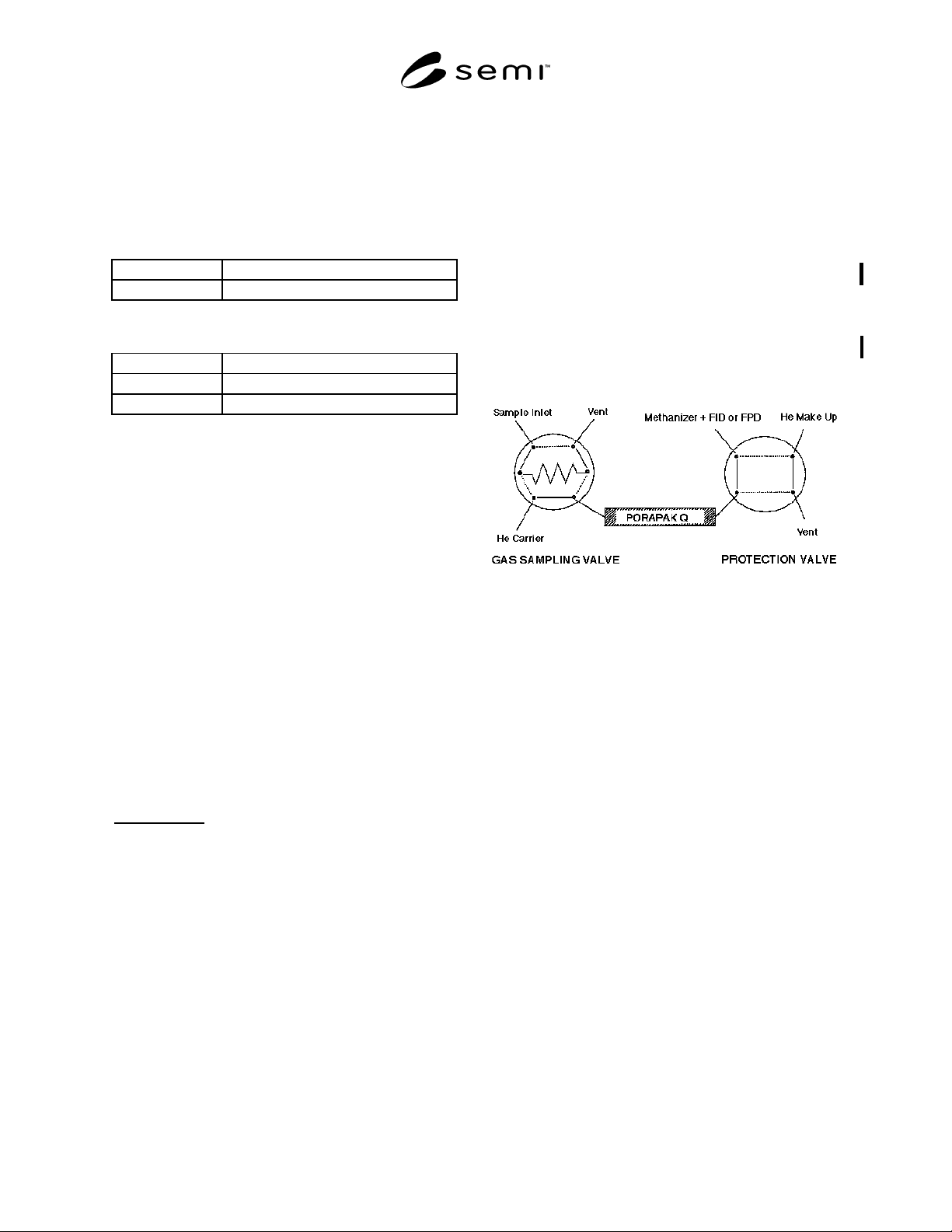
peak is eluted using same configuration as in Figure 1.
4.4.4.3 Repeat 4.4.4.1
4.4.4.4 Compare the average peak area of the
calibration standard to those of the arsine sample being
tested. Calculate the concentration of the hydrogen
sulfide, using the formula below. The result may not
exceed the specification in Section 2 of this Standard.
Sample Pea
k
Area
Standard Peak
Area
×
Concentration
of Standard
=
Concentration
of Sample
4.5 Water — This procedure is for the determination
of moisture in arsine using continuous flow electrolysis
of water in a phosphorus pentoxide (P
2
O
5
) cell.
4.5.1 Detection Limit — 1 ppm (vol/vol).
4.5.2 Instrument Parameters
4.5.2.1 Flow Requirements — Set the sample flow rate
and pressure in accordance with manufacturer’s
instructions.
4.5.3
Calibration Standards — Construct a calibration
curve which contains at least three points covering the
range of interest. Verify the standards employed
independently on a condensation dewpoint/frostpoint
hygrometer.
4.5.4
Operating Procedure
4.5.4.1 Obtain representative sample of gas to be
analyzed and direct to unit as with the standards.
4.5.4.2 Determine the moisture content in the sample
gas by comparing the indicated concentration with the
calibration curve constructed in 4.5.3. The result may
not exceed the specification in Section 2 of this
Standard.
NOTE 1: Carrier gases should contain less than 0.1 ppm
(mol/mol) carbon monoxide and less than 0.1 ppm (mol/mol)
carbon dioxide.
Figure 1
G. C. Configuration
NOTICE:
This specification does not purport to
address safety issues, if any, associated with its use. It
is the responsibility of the user of this specification to
establish appropriate safety and health practices and
determine the applicability of regulatory limitations
prior to use. SEMI makes no warranties or
representations as to the suitability of the specification
set forth herein for any particular application. The
determination of the suitability of the specification is
solely the responsibility of the user. Users are cautioned
to refer to manufacturer’s instructions, product labels,
product data sheets, and other relevant literature
respecting any materials or equipment mentioned
herein. This specification are subject to change without
notice.
The user’s attention is called to the possibility that
compliance with this specification may require use of
copyrighted material or of an invention covered by
patent rights. By publication of this specification, SEMI
takes no position respecting the validity of any patent
rights or copyrights asserted in connection with any
item mentioned in this specification. Users of this
specification are expressly advised that determination
of any such patent rights or copyrights, and the risk of
infringement of such rights, are entirely their own
responsibility.
Copyright by SEMI® (Semiconductor Equipment and Materials
International), 3081 Zanker Road, San Jose, CA 95134. Reproduction o
f
the contents in whole or in part is forbidden without express written
consent of SEMI.
SEMI C3.33-92 © SEMI 1987, 2003 1
SEMI C3.33-92 (Reapproved 0303)
STANDARD FOR BORON TRICHLORIDE (BCl
3
) (PROVISIONAL)
This standard was technically reapproved by the Global Gases Committee and is the direct responsibility of
the North American Gases Committee. Current edition approved by the North American Regional Standards
Committee on October 25, 2002. Initially available at www.semi.org December 2002; to be published March
2003. Originally published in 1987; previously published in 1992.
1 Description
1.1 Boron trichloride is a colorless gas at room
temperature and atmospheric pressure which fumes in
the presence of moist air. It has a choking odor.
2 Scope
NOTICE: This standard does not purport to address
safety issues, if any, associated with its use. It is the
responsibility of the users of this standard to establish
appropriate safety and health practices and determine
the applicability of regulatory or other limitations prior
to use.
3 Specifications
QUALITY: 99.9995% by wt. Liquid Phase
Impurities
Maximum Acceptable Level
(ppm)*
Chlorine (Cl
2
) 10 Vapor Phase
Hydrogen Chloride (HCl) 1 Vapor Phase
Phosgene (COCl
2
) 1 Vapor Phase
Aluminum (Al) 0.5 by wt. Liquid Phase
Calcium (Ca) 0.5 by wt. Liquid Phase
Copper (Cu) 0.5 by wt. Liquid Phase
Iron (Fe) 0.5 by wt. Liquid Phase
Magnesium (Mg) 0.5 by wt. Liquid Phase
Nickel (Ni) 0.5 by wt. Liquid Phase
Potassium (K) 0.5 by wt. Liquid Phase
Silicon (Si) 1 by wt. Liquid Phase
Sodium (Na) 0.5 by wt. Liquid Phase
TOTAL IMPURITIES 5 by wt. Liqiud Phase
* An analysis of significant figures has not been considered. The
number of significant figures will be based on analytical accuracy and
the precision of the provided procedure.
4 Physical Constants (for information only)
Metric Units US Units
Molecular weight 117.17 117.17
Boiling point at atm 12.4° C 54.3° F
Density of gas at 20° C
and 1 atm
5.326 kg/m
3
0.3325 lb/ft
3
Specific gravity 4.12 4.12
Density of liquid at
–118° C
1372.8 kg/m
3
85.76 lb/ft
3
NOTICE: SEMI makes no warranties or
representations as to the suitability of the standards set
forth herein for any particular application. The
determination of the suitability of the standard is solely
the responsibility of the user. Users are cautioned to
refer to manufacturer' s instructions, product labels,
product data sheets, and other relevant literature,
respecting any materials or equipment mentioned
herein. These standards are subject to change without
notice.
By publication of this standard, Semiconductor
Equipment and Materials International (SEMI) takes no
position respecting the validity of any patent rights or
copyrights asserted in connection with any items
mentioned in this standard. Users of this standard are
expressly advised that determination of any such patent
rights or copyrights, and the risk of infringement of
such rights are entirely their own responsibility.
Copyright by SEMI® (Semiconductor Equipment and Materials
International), 3081 Zanker Road, San Jose, CA 95134. Reproductio
n
of the contents in whole or in part is forbidden without express writte
n
consent of SEMI.