semi合集-English.pdf - 第4658页
SEMI C3.40-10 00 © SEMI 1989 , 2000 2 sample being tested. Calculate the conce ntration of carbon dioxide in the sample, using the formula below. The result may not exceed the s pecification in Section 2 of th i s Standa…
SEMI C3.40-1000 © SEMI 1989, 20001
SEMI C3.40-1000
STANDARD FOR CARBON TETRAFLUORIDE (CF
4
), VLSI GRADE
This standard was technically approved by the Global Gases Committee and is the direct responsibility of the
North American Gases Committee. Current edition approved by the North American Regional Standards
Committee on July 11, 2000. Initially available at www.semi.org September 2000; to be published October
2000. Originally published in 1989; previously published in 1992.
1 Description
1.1 Carbon tetrafluoride is an odorless, colorless,
nonflammable gas. It is a simple asphyxiant. It is also
known as tetrafluoromethane.
2 Specifications
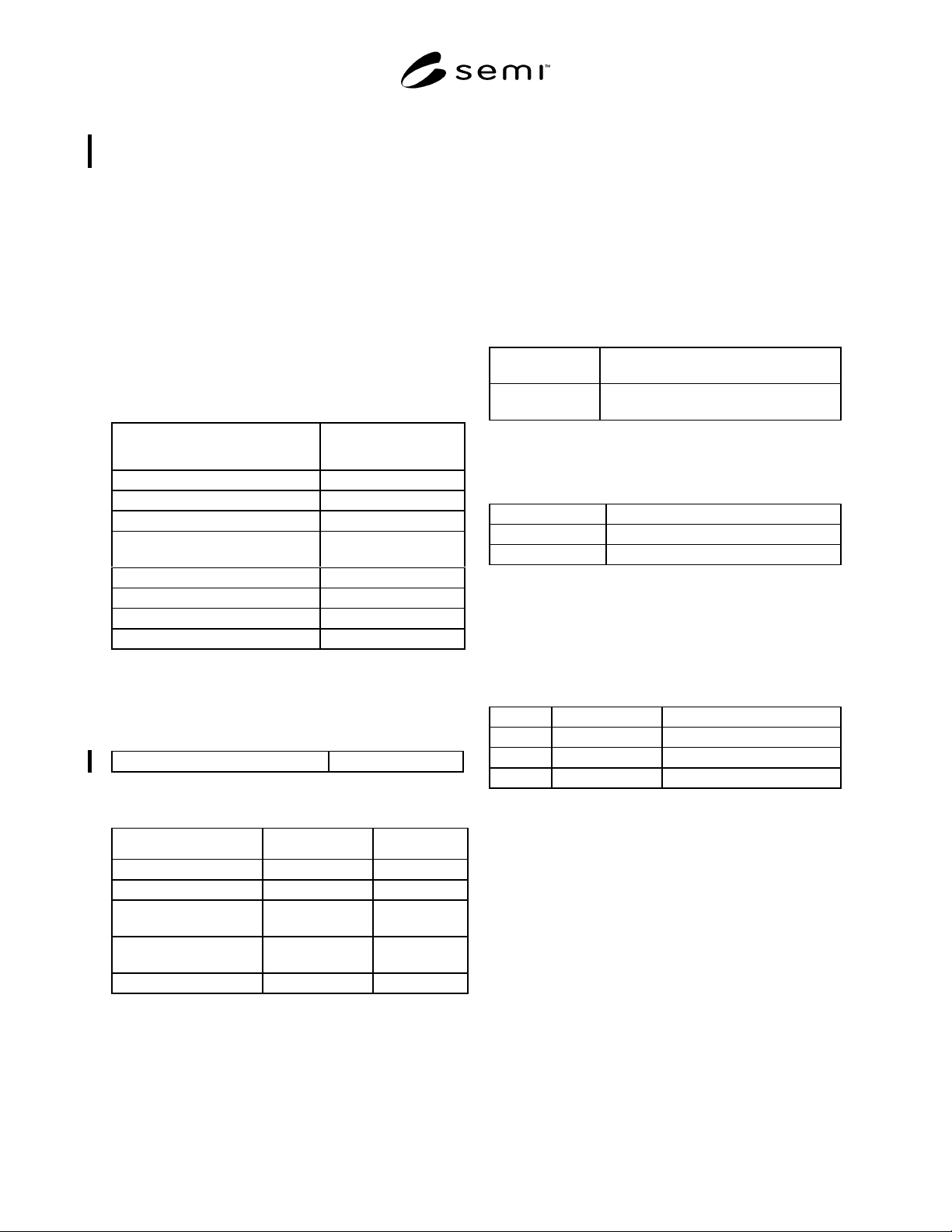
QUALITY: 99.997%
Impurities
Maximum Acceptable
Level (ppm) *
Carbon Dioxide (CO
2
)1
Carbon Monoxide (CO) 1
Nitrogen (N
2
)20
Other Halocarbons (CF
3
Cl,
CF
2
Cl
2
,CF
3
H)
1
Oxygen (O
2
)5
Sulfur Hexafluoride (SF
6
)1
Water (H
2
O) (v/v) 1
TOTAL IMPURITIES 30
* An analysis of significant figures has not been considered. The
number of significant figures will be based on analytical accuracy and
the precision of the provided procedure.
3 Chemical Specification
Total Hydrolyzable Fluorides as HF 1 ppm max.
4 Physical Constants (for in formation only)
Metric Units US Units
Molecular weight 88.005 88.005
Boiling point at 1 atm -128.0°C -198.4°F
Density of gas at 0°C
(32°F) and 1 atm
3.946 kg/m
3
0.246 lb/ft
3
Specific gravity of gas at
0°C and 1 atm
3.05 3.05
Density of liquid at -80°C 1317 kg/m
3
82.22 lb/ft
3
5 Analytical Procedures (Se e Notes 1 and 2,
and Figures 1 and 2.)
5.1 Carbon Dioxide — This procedure is for the
determination of carbon dioxide in carbon tetrafluoride
using a gas chromatograph with an ultrasonic detector.
5.1.1 Detection Limit — 0.5 ppm (mole/mole).
5.1.2 Instrument Parameters
5.1.2.1 Columns:
Column 1: Haysep D, 100/120 mesh, 4.6 m (15 ft) by
3.2 mm (1/8 in) OD ss or equivalent.
Column 2: Porapak QS, 100/120 mesh, 2.1 m (7 ft)
by 3.2 mm OD ss or equivalent.
5.1.2.2 Carrier Flow: 16 mL/min helium.
5.1.2.3 Temperatures:
Detector 120°C
Column 50°C
Valve 90°C
5.1.2.4 Sample Volume: 1.0 mL
5.1.2.5 Time Table — Determine the times for valve
switching and signal changes, and enter into the run
table.
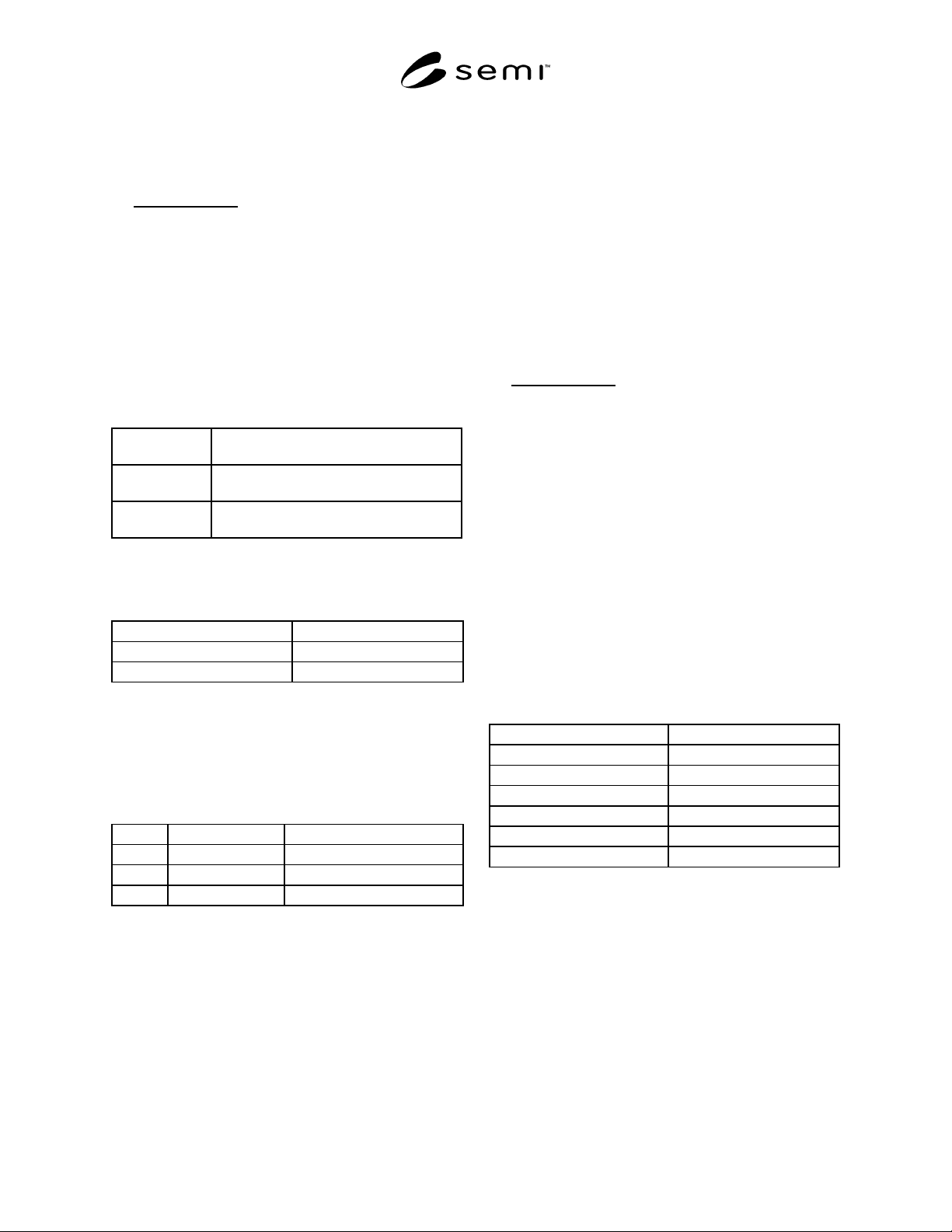
An example of a run table follows.
Valve On Off
10.01 *
29.20 *
3 0.01 12.00
* Valve left on until end of run.
5.1.3 Calibration Standard — 1–5 ppm carbon
dioxide and balance helium.
5.1.4 Operating Procedure
5.1.4.1 Inject the calibration standard into the column
using a gas sampling valve. Record retention times and
peak areas. The retention time for carbon dioxide is
approximately 16 minutes.
5.1.4.2 Inject the sample to be tested in the same
manner as the calibration standard. Record the retention
times and peak areas.
5.1.4.3 Repeat 5.1.4.1.
5.1.4.4 Compare the average peak areas of the
calibration standard to those of the carbon tetrafluoride
SEMI C3.40-1000 © SEMI 1989, 2000 2
sample being tested. Calculate the concentration of
carbon dioxide in the sample, using the formula below.
The result may not exceed the specification in Section 2
of this Standard.
Sample Peak Area
Standard Peak Area
×
Concentration
of Standard
=
Concentration
of Sample
5.2 Oxygen, Nitrogen and Carbon Monoxide — This
procedure is for the determination of oxygen, nitrogen,
and carbon monoxide in carbon tetrafluoride using a
gas chromatograph with an ultrasonic detector.
5.2.1 Detection Limits — 0.5 ppm (mole/mole) for
each impurity.
5.2.2 Instrument Parameters
5.2.2.1 Columns:
Column 3: Porapak QS, 100/120 mesh, 3.6 m (12 ft)
by 3.2 mm (1/8 in) OD ss or equivalent.
Column 4: Haysep D, 100/120 mesh, 4.6 m (15 ft) by
3.2 mm OD ss or equivalent.
Column 5: Molecular Sieve 13X, 45/60 mesh, 2.1 m
(7 ft) by 3.2 mm OD ss or equivalent.
5.2.2.2 Carrier Flow: 16 mL/min helium.
5.2.2.3 Temperatures:
Detector 120°C
Column 50°C
Valve 90°C
5.2.2.4 Sample Volume: 2.0 mL
5.2.2.5 Time Table — Determine the times for valve
switching and signal changes, and enter into the run
table.
An example of a run table follows.
Valve On Off
10.01 *
29.20 *
3 0.01 12.00
* Valve left on until end of run.
5.2.3 Calibration Standard — 1–5 ppm (mole/mole)
each nitrogen, oxygen and carbon monoxide, balance
helium.
5.2.4 Operating Procedure
5.2.4.1 Inject the calibration standard into the column
using a gas sampling valve. Record retention times and
peak areas. The approximate retention times are:
oxygen 11.1 minutes, nitrogen 11.6 minutes, carbon
monoxide 14.5 minutes.
5.2.4.2 Inject the sample to be tested in the same
manner as the calibration standard. Record the retention
times and peak areas.
5.2.4.3 Repeat 5.2.4.1.
5.2.4.4 Compare the average peak areas of the
calibration standard to those of the carbon tetrafluoride
sample being tested. Calculate the concentrations of
oxygen, nitrogen and carbon monoxide in the sample,
using the formula below. The results may not exceed
the specifications in Section 2 of this Standard.
Sample Peak Area
Standard Peak Area
×
Concentration
of Standard
=
Concentration
of Sample
5.3 Fluorocarbon and Chlorofluorocarbon Impurities
— This procedure is for the determination of the
volatile organic impurities in carbon tetrafluoride using
a gas chromatograph with a flame ionization detector.
5.3.1 Detection Limits — 0.5 ppm (mole/mole) for
each impurity.
5.3.2 Instrument Parameters
5.3.2.1 Column: 1% SP-1000 on Carbopak B (60/80),
7.3 m (24 ft) by 3.2 mm (1/8 in) OD ss or equivalent.
5.3.2.2 Carrier Flow: 40 mL/min helium.
5.3.2.3 Support Gases: Set the flow rates as specified
by the instrument manufacturer.
5.3.2.4 Temperatures:
Injection Port 200°C
Detector 250°C
Initial Oven 35°C
Pre-Program Hold 7 min
Temperature Rise 10°C/min
Final Oven 150°C
Final Hold 10 min
5.3.2.5 Sample Volume: 2 mL.
5.3.3 Calibration Standard — 1–10 ppm (by volume)
desired impurities in helium. Practical impurities may
be trifluoromethane (CHF
3
), hexafluoroethane (C
2
F
6
),
dichlorodifluoromethane (CCl
2
F
2
), and chlorotrifluo-
romethane (CClF
3
).
5.3.4 Operating Procedure
5.3.4.1 Attach a stainless steel diaphragm two-stage
regulator to the standard cylinder. Connect the regulator
to the 6 port chromatographic sampling valve.
SEMI C3.40-1000 © SEMI 1989, 20003
5.3.4.2 Purge the sampling lines with the standard for
at least one minute.
5.3.4.3 Pressurize the sampling lines to 5 psig.
5.3.4.4 Inject the standard into the gas chromatograph,
and start the scan. Record the retention times and peak
areas. Order of elution for the above mentioned
standard is carbon tetrafluoride, trifluoromethane,
hexafluoroethane, chlorotrifluoromethane, and
dichlorodifluoromethane.
5.3.4.5 Inject the sample to be tested in the same
manner as the calibration standard.
5.3.4.6 Repeat 5.3.4.1–5.3.4.4.
5.3.4.7 Compare the average peak areas of the
calibration standard to those of the carbon tetrafluoride
sample being tested. Calculate the concentration of each
of the impurities using the formula below. The results
may not exceed the specifications in Section 2 of this
Standard.
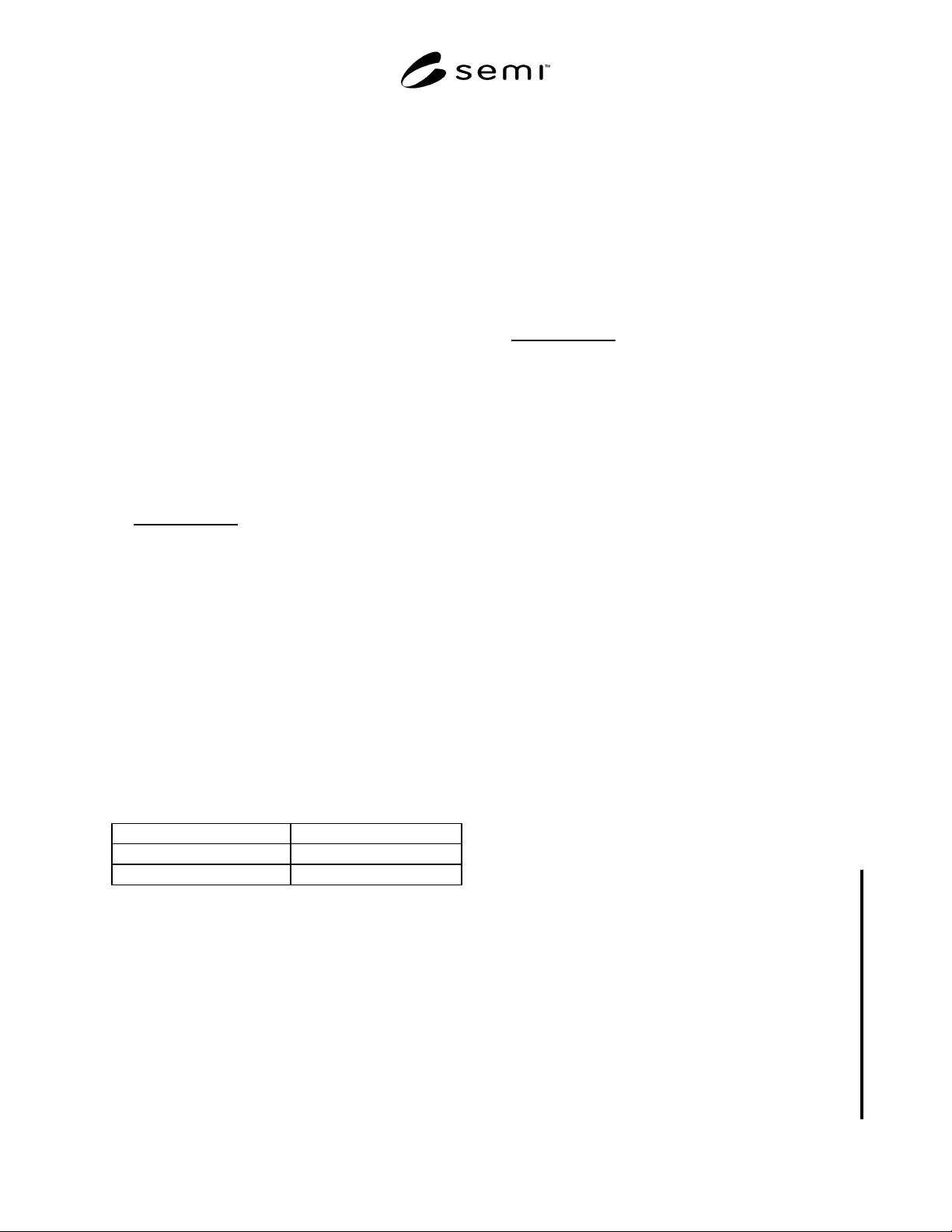
Sample Peak Area
Standard Peak Area
×
Concentration
of Standard
=
Concentration
of Sample
5.4 Sulfur Hexafluoride — This procedure is for the
determination of sulfur hexafluoride in carbon
tetrafluoride using a gas chromatograph with a thermal
conductivity detector. (See Figure 2.)
5.4.1 Detection Limit — 0.5 ppm.
5.4.2 Instrument Parameters
5.4.2.1 Column: Super Q, 80/100 mesh, 4.9 m (16 ft)
by 1.75 mm (1/16 in) ID, 3.2 mm (1/8 in) OD, ss or
equivalent.
5.4.2.2 Carrier Flow: 19 mL/min helium.
5.4.2.3 Temperatures:
Detector 100°C
Oven 70°C
Gas sampling valve 70°C
5.4.2.4 Sample Volume: 1 mL.
5.4.3 Calibration Standard — 1 ppm sulfur
hexafluoride, balance helium.
5.4.4 Operating Procedures
5.4.4.1 Inject the calibration standard into the column
using a gas sampling valve. Record retention time and
peak area.
5.4.4.2 Inject the sample to be tested in the same
manner as the calibration standard. Record the retention
times and peak areas.
5.4.4.3 Repeat 5.4.4.1.
5.4.4.4 Compare the average peak areas of the
calibration standard to those of the carbon tetrafluoride
sample being tested. Calculate the concentration of
sulfur hexafluoride using the formula below. The result
may not exceed the specification in Section 2 of this
Standard.
Sample Peak Area
Standard Peak Area
×
Concentration
of Standard
=
Concentration
of Sample
5.5 Water — This procedure is for the determination
of trace moisture (water) in carbon tetrafluoride using a
continuous flowing electrolytic hygrometer.
5.5.1 Detection Limit — 1.0 ppm (vol/vol) or -76°C
(-105°F).
5.5.2 Flow Requirements — Set the sample pressure
and flow rate in accordance with the instrument
manufacturer’s instructions.
5.5.3 Operation Check — Check the electrolytic
hygrometer periodically. A gas, containing a known
amount of water, should be passed through the
hygrometer. Agreement between the electrolytic
hygrometer and the moisture standard should be within
their relative accuracies.
5.5.4 Operating Procedure
5.5.4.1 Obtain a continuous flow sample of gas, from
the CF
4
source, using a clean, passivated stainless steel
line which has been purged dry after exposure to
ambient moisture. (See Notes 3 and 4.)
5.5.4.2 After prepurging with a dry gas, allow the
sample gas to flow through the sampling system and the
electrolytic moisture analyzer until a stable reading is
obtained. The result may not exceed the specification in
Section 2 of this standard.
5.6 Hydrolyzable Fluorides as HF — This procedure
is for the determination of hydrolyzable fluorides in
carbon tetrafluoride using fluoride ion selective
electrode.
5.6.1 Detection Limit — Detection limits should be
checked for any new implementation of a method.
Detection limits below 0.1 ppm have been determined
with this method. Detection limits can be improved by
increasing the volume of gas sampled.
5.6.2 Equipment
5.6.2.1 mV meter (0.1 mV scale)
5.6.2.2 Reference electrode (single junction type)