semi合集-English.pdf - 第4665页
SEMI C3.32-03 01 © SEMI 1987 , 2001 3 4.3.4.3 Fl uorocarbon Needle Valve — T wo 6.4 mm (1/4") needle valves (desi gnated as V1 and V2). (See Figure 3.) 4.3.4.4 Fluorocarbon Ball Valve — On e 6 . 4 m m (1/4") ba…

SEMI C3.32-0301 © SEMI 1987, 2001 2
4.1.4.4 Determine the time at which ethane elutes
from the first column and absorbs onto the second
column so one can vent the chlorine. Inject the
calibration ethane standard and record the retention
time of ethane obtained without returning the valve to
the load position. Multiply this time by 0.6. The result
will be the time during the analysis at which the
injection valve should be returned to the load position,
backflushing the chlorine to vent.
Repeat the injection of the ethane calibration standard,
including the backflush, to ensure that enough time has
passed to allow elution of ethane onto the second
column.
4.1.4.5 Inject the remaining standards using the
backflush technique. Record the retention times and
peak areas.
4.1.4.6 Analyze the chlorine sample to be tested in the
same manner as in 4.1.4.5. Repeat the sample injection
until peak areas of the impurity of interest agree within
5%.
4.1.4.7 Analyze each of the calibration standards again
as in 4.1.4.5.
4.1.4.8 Compare the average peak areas of the
calibration standards to those of the chlorine sample
being tested. Calculate the concentration of each
impurity, using the formula below. The results may not
exceed the specifications in Section 2 of this standard.
Sample Peak Are
a
Standard Peak Are
a
×
Concentratio
n
of Standard
=
Concentratio
n
of Sample
4.2 Oxygen and Nitrogen — This procedure is for the
determination of oxygen and nitrogen in chlorine. The
sample shall be vapor phase and analyzed using a gas
chromatograph with a thermal conductivity detector.
(See Figure 2 and Notes 1 and 2.)
4.2.1
Detection Limits — 2 ppm (v/v) oxygen, 5 ppm
(v/v) nitrogen.
4.2.2
Instrument Parameters
4.2.2.1 Injection Valve — 10 port corrosion-resistant.
4.2.2.2
Sample Volume — 2 mL.
4.2.2.3 Columns:
Column 1: Porapak Q, 1.8 m (6 ft) by 3.2 mm (1/8 in)
OD ss or equivalent.
Column 2: Molecular sieve 13×, 3.1 m (10ft) by 3.2 mm
OD ss or equivalent.
4.2.2.4 Carrier Flow — 20 mL/min he lium.
4.2.2.5
Temperature:
Column 30°C
Detector 50°C
4.2.3 Calibration Standard — 10–40 ppm (v/v) each
component in helium.
4.2.4
Operating Procedure
4.2.4.1 Place the 10 port valve in the sample load
position.
4.2.4.2 Inject the standard, wait one minute, then
return the valve to the sample load position to backflush
the principal gas to vent while allowing the oxygen and
nitrogen to pass to the analytical column. Record the
retention times and peak areas.
4.2.4.3
Inject the standard at least three times. All
peak areas for a specific impurity should agree within
5%.
4.2.4.4
Inject the chlorine sample to be tested in the
same manner as in 4.2.4.2 and 4.2.4.3. Record the
retention times and peak areas.
4.2.4.5
Repeat 4.2.4.2 and 4.2.4.3.
4.2.4.6 Compare the average peak areas of calibration
standards with that of the chlorine sample being tested.
Calculate the concentrations of oxygen and nitrogen,
using the formula below. The results may not exceed
the specifications in Section 2 of this standard.
Sample Peak Are
a
Standard Peak Are
a
×
Concentratio
n
of Standard
=
Concentratio
n
of Sample
4.3
Trace Elements — This procedure gives
instructions for the determination of trace elements in
liquid phase chlorine using inductively coupled plasma
mass spectrometry (ICP-MS). (See Note 4.)
4.3.1
Detection Limit — (See Note 4.)
4.3.2 Instrument Parameters — (See Note 4.)
4.3.3 Calibration Standards — (See Note 4.) All
instrument calibration standards should be prepared
from NIST-traceable reference standards.
4.3.4
Sample Collection Apparatus — (See Notes 5
and 6 and Figures 3 and 4.)
4.3.4.1 Cylinder Connector — Stainless steel, or other
suitable material, dependent on the cylinder valve used.
4.3.4.2
Fluorocarbon Tubing — 6.4 mm (1/4") and 3.2
mm (1/8") outer diameters required, lengths dependent
on construction of apparatus.

SEMI C3.32-0301 © SEMI 1987, 20013
4.3.4.3 Fluorocarbon Needle Valve — Two 6.4 mm
(1/4") needle valves (designated as V1 and V2). (See
Figure 3.)
4.3.4.4
Fluorocarbon Ball Valve — One 6.4 mm
(1/4") ball valve and one 3.2 mm (1/8") ball valve
(designated as V3 and V4, respectively). (See Figure
3.)
4.3.4.5
Fluorocarbon T-Joint — One 6.4 mm (1/4") T-
joint.
4.3.4.6 Fluorocarbon Cylinder Union — One 6.4 mm
(1/4") to 15.9 mm (5/8") iron pipe size female pipe
thread adapter to attach to the stainless steel cylinder
connector.
4.3.4.7
Fluorocarbon Reducer — One 6.4 mm (1/4")
to 3.2 mm (1/8") reducing union.
4.3.4.8 Flask Connector — One Plasmatech #16F424
flask connector, or similar, attached to a cap for the 100
mL sampling flask.
4.3.4.9
Sampling Flasks — 100 mL polypropylene
volumetric flask.
4.3.4.10 Nitrogen Source — A source of high-purity
nitrogen to purge the sampling system prior to and after
sampling and for evaporation.
4.3.4.11
Scrubber Source — A caustic scrubber source
to neutralize chlorine from the sampling process. The
scrubber is connected to an eductor tube, with the
vacuum created by an N
2
source regulated at 20 psi.
4.3.5 Operating Procedure
4.3.5.1 Assemble the system according to Figures 3
and 4, ensuring that the connections are leak tight.
4.3.5.2
Wrap Teflon tape around the threads of a 100
mL volumetric flask to ensure a good seal. Connect the
100 mL polypropylene flask to the flask connector as
shown in Figure 3. All 100 mL volumetric flasks used
for sample collection should be prepared in a similar
manner.
4.3.5.3
Clean the exterior of the cylinder CGA by
rinsing it with (in succession) 10% HNO
3
/DI H
2
O,
isopropanol/DI H
2
O, and DI H
2
O. The CGA must be
free of residue. The CGA is then cleaned and dried with
a cotton swab. Dry the exterior of the CGA with the
high-purity N
2
. Repeat the process for the nut and
gland. The cylinder CGA must be completely dry prior
to connecting the nut and gland.
4.3.5.4
Invert the cylinder with a cylinder inverter and
connect the cylinder CGA to the nut and gland.
4.3.5.5
Purge the system by opening V1 and V2 and
allowing high purity N
2
to flow through the system at
5–10 psig for a minimum of three minutes. The ball
valves (V3 and V4) remain in the open position.
4.3.5.6
Close V1 and V2. To condition the sampling
system, open the cylinder valve, then slowly open V2 to
allow Cl
2
to flow into the sample flask. After collecting
70–100 mL of Cl
2
, close the cylinder valve and open
V1 to purge the system.
4.3.5.7 Discard the initial Cl
2
sample by passing it
through to the scrubber, remove the flask and replace it
with a labeled sample flask. Continue to purge the
system for at least two minutes. Close V1 and V2. Open
the cylinder valve, then slowly open V2.
4.3.5.8
Allow 100 g of sample to be introduced into
the sample flask. Once this is completed, close V2, then
close the cylinder valve. Open V1 and V2 to allow for
purging of the Cl
2
in the sample flask with high purity
N
2
flowing through the system at 5 psig. This will
purge the Cl
2
at a rate of 7–10 gms per minute.
4.3.5.9 When the sample has been flushed, replace the
sample flask with another flask. Loosely cap the sample
flask to allow for any residual Cl
2
to evaporate. If
additional samples from the same cylinder are desired,
repeat Steps 4.3.5.5 through 4.3.4.9.
4.3.5.10
Close V1 and disconnect the cylinder valve
connector from the cylinder valve. Return the cylinder
to the upright position. Rinse the cylinder CGA and nut,
gland with DI H
2
O, and dry with N
2
. Remove the
cylinder from the cylinder inverter.
4.3.5.11
Repeat Steps 4.3.5.3 to 4.3.5.10 for additional
cylinders.
4.3.5.12
After obtaining all samples of interest, hand
dry the connector and place it into an oven to prevent
corrosion and build-up of condensation. Clean the
tubing and valve system with a 10% HNO
3
/DI H
2
O
solution and store in a 25% HNO
3
/DI H
2
O solution.
4.3.5.13 Fill each sample flask with a solution of 5%
ultrapure HNO
3
/DI H
2
O spiked with 25 ppb of an
internal standard (such as indium) up to the graduation
mark. Allow the samples to digest in the solution in the
flasks for a minimum of one hour. (See Note 7.)
4.4
Water — This procedure is for the determination
of moisture in gas phase chlorine using a continuous
flow electrolysis of water in a phosphorous pentoxide
(P
2
O
5
) cell. (See Notes 2 and 8.)
4.4.1 Detection Limit — 1 ppm (vol/vol).
4.4.2 Flow Rate — Set the sample flow rate and
pressure in accordance with the instrument
manufacturer's instructions.
SEMI C3.32-0301 © SEMI 1987, 2001 4
4.4.3 Calibration Standards — Construct a calibration
curve which contains at least two points covering the
range of interest.
4.4.4
Operating Procedure
4.4.4.1 Leak check the entire system using helium and
a helium leak detector prior to use.
4.4.4.2 Pre-purge through the regulator/cross-purge
assembly with a dry gas of known moisture content
until the moisture content is measured below 1 ppm
(vol/vol).
4.4.4.3
Direct samples of two standards, independently
verified with a dewpoint/frostpoint hygrometer,
spanning the range of moisture content of interest to the
analyzer. After a stable reading is obtained, record the
instrument's response to each standard.
4.4.4.4
Obtain a representative sample of the gas to be
analyzed and direct it to the unit as with the standards.
After a stable reading is obtained, record the
instrument’s response.
4.4.4.5
Construct a calibration curve from the standard
data and determine the moisture content in the sample
gas. The result may not exceed the specification in
Section 2 of this standard.
4.5
Notes
NOTE 1: Sample system should be constructed entirely of
stainless steel or other suitable material due to the corrosive
nature of the product.
NOTE 2: Sample must be appropriately vented for health and
safety of operating personnel.
NOTE 3: Individual standards are required for accuracy and
identification by retention time.
NOTE 4: Other accepted instrumental techniques are also
appropriate for this analysis. In addition, operating procedures
for ICP-MS instruments vary, depending on the manufacturer.
In all cases, refer to individual instrument vendor instructions.
NOTE 5: All sampling flasks are leached with a 25%
HNO
3
/H
2
O solution for at least 24 hours, rinsed thoroughly
with DI H
2
O, and filled with DI H
2
O for at least 24 hours
prior to use. On the day of sampling, flasks are rinsed
thoroughly with DI H
2
O and dried with N
2
prior to system
setup.
NOTE 6: The tubing and Fluorocarbon valves are soaked in a
25% HNO
3
/DI H
2
O solution prior to use (either apart or pre-
assembled). The tubing and valves are rinsed thoroughly with
DI H
2
O and dried with high-purity N
2
prior to system setup.
NOTE 7: A different digestion solution may be used,
depending on possible interferences with a given analysis
technique.
NOTE 8: All wetted surfaces, including P
2
O
5
hygrometer and
sample system, are to be of 316 stainless steel or other
suitable material.
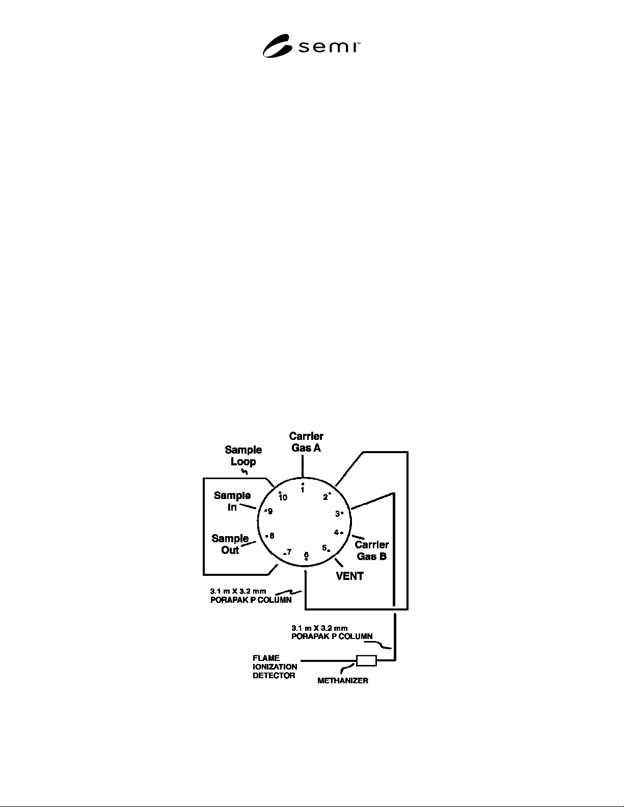
Figure 1
Carbon Monoxide, Carbon Dioxide, and Hydrocarbons Determination