semi合集-English.pdf - 第4758页
SEMI C6.2-93 © SEMI 1989, 2002 3 NOTICE: SEMI makes no warranties or representatio ns as to the suitability of th e standards set forth herein for any particular application. Th e determination of the suitability of the …
SEMI C6.2-93 © SEMI 1989, 2002 2
3.7 Standard Error (SEC)
SE
C
=
S
M
2
N
M
+
S
B
2
N
M
1
2
4 Apparatus
4.1 Particle Counter — An instrument suitable for
counting particles in gaseous oxygen with a counting
efficiency of 50 percent at 0.02 micrometers as
determined by the manufacturer of the particle counter.
Condensation nucleus counters (CNCs) typically satisfy
this requirement.
4.2 Pressure Reducer — An accessory required for
counters operated at atmospheric pressure, it should
preferably use expansion of the gas through a critical
orifice.
5 Test Method
NOTE 3: The details of sampling configuration,
measurement procedure, and instrument calibration procedure
and frequency must be agreed upon by the user and supplier,
taking into account good engineering practice.
5.1 Determine the average observed concentration of
counts in the background (
B
X ) by passing air or
nitrogen or oxygen believed to be free of particles of
0.02 micrometers or larger in diameter, through the
instrument and recording the total number of counts.
Count a minimum of 8 sample intervals, each at least
25 standard liters (0.95 SCF) or 30 minutes, whichever
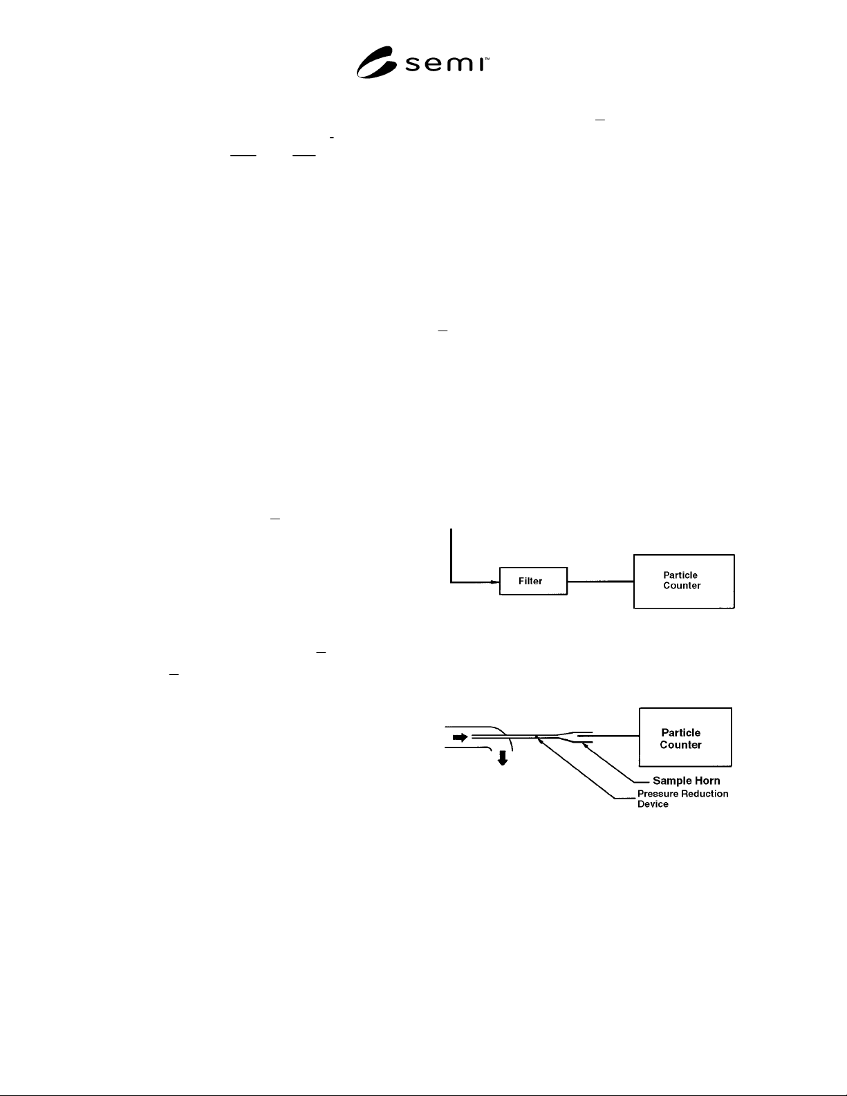
is greater. A suggested assembly for performing this
test, using a filter which removes particles in this size
range, is shown in Figure 1. Calculate
B
X as defined in
Section 3.
B
X must not exceed 2 particles per 25
standard liters.
5.2 The sampling point should be at outlet of system,
and sampling lines should be as short as possible.
5.3 A suggested sampling probe configuration for
turbulent main line flow is shown in Figure 2. The flow
rate in the sampling tube at pipeline pressure should be
set so that the mean sampling flow velocity at the probe
inlet matches as closely as possible the axial flow
velocity in the pipeline. The pitot sampling tube ID
should be no less than 2 mm (0.08 inch). The orifice
and sampling horn should be sized so that the mean
flow velocity at the particle counter probe inlet matches
the axial flow velocity in the horn as closely as
possible.
5.4 Count the particles in each of at least 8 sample
intervals. Each sample interval must be at least 25
standard liters or 30 minutes, whichever is greater.
Record the number of counts and the sample volume
for each interval. Calculate
C
X and SE
C
, as defined in
Section 3.
6 Specification
6.1 Maximum Permissible Particle Concentration —
20. particles per 25 standard liters as determined by the
instrument specified in Section 4.
6.2 The specification will be considered met if the
calculated concentration of particles plus two standard
errors does not exceed 20. particles per 25 standard
liters, i.e.:
C
X + 2*SE
C
≤ 20. Particles/25 standard liters
7 Report
7.1 The report shall contain the values of all the
variables defined in Section 3.
8 Precision
8.1 This test procedure defines the requirements to
satisfy the specification at the 95 percent confidence
level.
Figure 1
Suggested Assembly for Determining Particle
Counter Background
Figure 2
Schematic Diagrams of Configurations of
Different Merit for Obtaining Particle Samples
from Pipelines

SEMI C6.2-93 © SEMI 1989, 2002 3
NOTICE: SEMI makes no warranties or representations as to the suitability of the standards set forth herein for any
particular application. The determination of the suitability of the standard is solely the responsibility of the user.
Users are cautioned to refer to manufacturer’s instructions, product labels, product data sheets, and other relevant
literature respecting any materials mentioned herein. These standards are subject to change without notice.
The user’s attention is called to the possibility that compliance with this standard may require use of copyrighted
material or of an invention covered by patent rights. By publication of this standard, SEMI takes no position
respecting the validity of any patent rights or copyrights asserted in connection with any item mentioned in this
standard. Users of this standard are expressly advised that determination of any such patent rights or copyrights, and
the risk of infringement of such rights, are entirely their own responsibility.
Copyright by SEMI® (Semiconductor Equipment and Materials
International), 3081 Zanker Road, San Jose, CA 95134. Reproduction o
f
the contents in whole or in part is forbidden without express written
consent of SEMI.

SEMI C9.1-93 © SEMI 1993, 2002 1
SEMI C9.1-93 (Reapproved 1102)
GUIDE FOR ANALYSIS OF UNCERTAINTIES IN GRAVIMETRICALLY
PREPARED GAS MIXTURES
This guide was technically approved by the Global Gases Committee and is the direct responsibility of the
North American Gases Committee. Current edition approved by the North American Regional Standards
Committee on July 21, 2002. Initially available at www.semi.org October 2002; to be published November
2002. Originally published in 1993.
1 Purpose
1.1 This document is intended to provide the minimum
criterion for the analysis of uncertainty associated with
preparation and use of gravimetric gas mixtures used
for calibrating analytical instruments to determine
whether various SEMI impurity specification are
satisfied.
2 Scope
2.1 This guideline is intended for preparation of binary
gas mixtures using individual cylinders.
2.2 It is the intent of this document to provide general
guidelines for preparation of calibration gas mixtures in
compliance with ISO 6142, with additional
requirements to meet the needs of the semiconductor
industry.
2.3 This guideline is applicable only to gaseous
components which do not react between themselves or
with the cylinder walls, and to condensable components
which are totally vaporized under the test conditions. It
is not intended for moisture calibration mixtures.
2.4 This standard does not purport to address safety
issues, if any, associated with its use. It is the
responsibility of the users of this standard to establish
appropriate safety health practices and determine the
applicability or regulatory limitations prior to use.
3 Referenced Standards
3.1 ISO Standards
1
ISO 6142 — Gas Analysis; Preparation of calibration
gas mixtures - weighing methods.
Addendum 1 to ISO 6142 - Annex — Precautions to be
taken when weighing, handling and filling cylinders.
4 Weight Traceability
4.1 The weights used to prepare the gas mixtures or
certify the balance should be Class S1-tested at least
1 International Organization for Standardization, ISO Central
Secretariat, 1, rue de Varembé, Case postale 56, CH-1211 Geneva 20,
Switzerland. Telephone: 41.22.749.01.11; Fax: 41.22.733.34.30
Website: www.iso.ch
annually with reference standards traceable to the
National Institute of Standards and Technology or to
another national standards organization.
5 Acceptable Mixture Criteria
5.1 Cylinder — Cylinder must comply with National or
International Codes. The type of cylinder used for
containment of the gas mixture may affect the stability
of the mixture. Historical and experimental data should
be requested from the supplier on the stability of similar
mixtures. The cylinder material should be chosen based
on its compatibility with the gas mixture.
5.2 Valve — The recommended valve should be
packless type valve and the constuction materials
selected according to their compatibility with the gas
mixture.
5.3 Homogenous Mixture — The cylinder and its
contents should be at room temperature prior to use.
The cylinder mixture components must be mixed to
insure a homogenous mixture.
5.4 Stability — The gas mixture will have a
demonstrated stability within the acceptable relative
uncertainties given in Section 6 for a period of 1 year.
The minimum useful pressure should be in accordance
with the suppliers recommendations.
5.5 Balance Gas Purity — The balance gas should be
determined to contain less than 1% of the relative
concentration for the minor component.
5.6 Minor Component Purity — The product used for
the minor component addition should be analyzed to
verify its composition.
5.7 Analysis — Confirmation analysis of the
calibration mixture should be performed to determine if
any gross weighing errors occurred.
6 Acceptable Relative Uncertainties
6.1 Using the ISO procedures the acceptable maximum
relative uncertainties for the component of interest are
given below.