semi合集-English.pdf - 第479页
SEMI E68-0997 © SEMI 1997, 2003 4 Figure 3 Two-Minute Power Int erruption Warm-Up Time 12.1.1 Final steady-state value of the DUT. 12.1.2 Time to achieve a steady state value . 12.1.3 Use Table 1 to summarize warm-up tim…
SEMI E68-0997 © SEMI 1997, 2003 3
Table 1 Format for Data Presentation
Warm-up Time Date:____________
± 1% FS Time to
Achieve
Steady State
Steady State
Value
Cold Start
Power Interruption
10.4 Cold Start — Apply power to the DUT and
continue collecting data until the indicated flow
achieves a steady state value.
10.5 Power Interruption — Continue to collect data
while disconnecting power from the test unit for 120 ±
10 seconds. Reconnect power to the DUT and monitor
indicated flow until steady state is again achieved.
11 Data Analysis
11.1 Graph the data collected from the six test
scenarios as directed in Section 10.
11.2 The time required for the DUT to achieve a steady
state value can be visually determined from the graph
of each test scenario. This data can be used to predict
the warm-up times required by an MFC experiencing a
field condition similar to the test scenario.
12 Data Presentation
12.1 For the two tests in Section 10, plot DUT
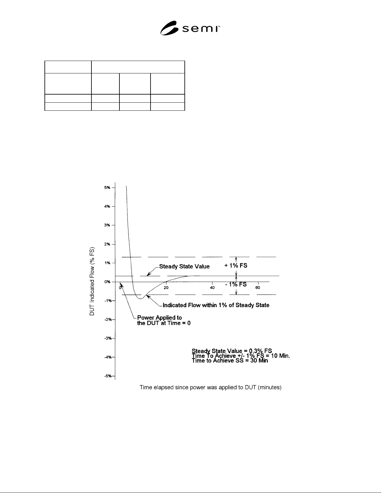
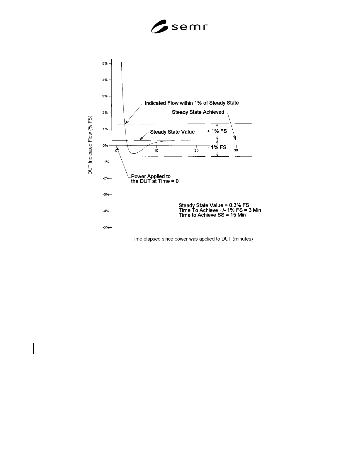
indicated flow vs. time as illustrated in Figures 2 and 3.
Note the following on these graphs and in Table 1.
Figure 2
Cold Start Warm-Up Time
SEMI E68-0997 © SEMI 1997, 2003 4
Figure 3
Two-Minute Power Interruption Warm-Up Time
12.1.1 Final steady-state value of the DUT.
12.1.2 Time to achieve a steady state value.
12.1.3 Use Table 1 to summarize warm-up times associated with each of the test scenarios.
13 Precision and Bias
13.1 Precision and bias in this test are a function of the uncertainty of the measurement equipment used. The tester
or end user is responsible for determining the precision and bias of a particular setup and test.
NOTICE: SEMI makes no warranties or representations as to the suitability of the standards set forth herein for any
particular application. The determination of the suitability of the standard is solely the responsibility of the user.
Users are cautioned to refer to manufacturer’s instructions, product labels, product data sheets, and other relevant
literature respecting any materials mentioned herein. These standards are subject to change without notice.
The user’s attention is called to the possibility that compliance with this standard may require use of copyrighted
material or of an invention covered by patent rights. By publication of this standard, SEMI takes no position
respecting the validity of any patent rights or copyrights asserted in connection with any item mentioned in this
standard. Users of this standard are expressly advised that determination of any such patent rights or copyrights, and
the risk of infringement of such rights, are entirely their own responsibility.
Copyright by SEMI® (Semiconductor Equipment and Materials
International), 3081 Zanker Road, San Jose, CA 95134. Reproduction o
f
the contents in whole or in part is forbidden without express written
consent of SEMI.

SEMI E69-0298 © SEMI 1998, 2003 1
SEMI E69-0298 (Reapproved 1103)
TEST METHOD FOR DETERMINING REPRODUCIBILITY AND ZERO
DRIFT FOR THERMAL MASS FLOW CONTROLLERS
This test method was technically approved by the Global Gases Committee and is the direct responsibility of
the North American Gases Committee. Current edition approved by the North American Regional Standards
Committee on July 27, 2003. Initially available at www.semi.org October 2003; to be published November
2003. Originally published February 1998.
1 Purpose
1.1 The purpose of this document is to provide a
standardized method to quantify the reproducibility and
zero drift of a thermal mass flow controller.
1.2 The intent of this document is not to suggest any
specific testing program but to specify the test method
to be used when testing for parameters that are covered
by this method. The user might use this document to
check significant performance characteristics, such as
reproducibility and zero drift, under a set of closely
controlled test conditions.
1.3 The significance of the accuracy calculations in this
method is to allow an MFC user to transfer a process
from one manufacturing tool to another and to
exchange MFCs within a single manufacturing tool
while maintaining process control.
2 Scope
2.1 This document describes the conditions and
procedures for testing the reproducibility and zero drift
of thermal mass flow controllers (MFCs). Because of
the generic nature of this document, not all test
procedures apply to all types of MFCs.
2.2 This document provides a common basis for
communication between manufacturers and users.
NOTICE: This standard does not purport to address
safety issues, if any, associated with its use. It is the
responsibility of the users of this standard to establish
appropriate safety and health practices and determine
the applicability of regulatory or other limitations prior
to use.
3 Limitations
3.1 It is not practical to evaluate performance under all
possible combinations of operating conditions. This test
procedure should be applied under laboratory
conditions; its intent is to collect sufficient data to form
a judgement of the field performance of the MFC being
tested.
4 Referenced Standards
4.1 SEMI Standard
SEMI E28 — Guideline for Pressure Specifications of
the Mass Flow Controller
4.2 ANSI Standards
1
ANSI C39.5 — Safety Requirements for Electrical and
Electronic Measuring and Controlling Instrumentation
ANSI C42.100 — Dictionary of Electrical and
Electronics Terms
ANSI MC4.1 — Dynamic Response Testing of Process
Control Instrumentation
4.3 ASME Document
2
ASME MFC-1M — Glossary of Terms Used in the
Measurement of Fluid Flow in Pipes
4.4 IEC Standards
3
IEC 160 — Standard Atmospheric Conditions for Test
Purposes
IEC 546 — Methods of Evaluating the Performance of
Controllers with Analogue [sic] Signals for Use in
Industrial Process Control
4.5 ISA Documents
4
ISA S7.3 — Quality Standards for Instrument Air
ISA S51.1 — Process Instrumentation Terminology
ANSI/ISA-1 979 (reaffirmed 1993)
1 American National Standards Institute, Headquarters: 1819 L
Street, NW, Washington, DC 20036, USA. Telephone: 202.293.8020;
Fax: 202.293.9287, New York Office: 11 West 42nd Street, New
York, NY 10036, USA. Telephone: 212.642.4900; Fax:
212.398.0023, Website: www.ansi.org
2 American Society of Mechanical Engineers, Three Park Avenue,
New York, NY 10016-5990, USA. Telephone: 800.843.2763
(U.S./Canada), 95.800.843.2763 (Mexico), 973.882.1167 (outside
North America), Website: www.asme.org
3 International Electrotechnical Commission, 3, rue de Varembé,
Case Postale 131, CH-1211 Geneva 20, Switzerland. Telephone:
41.22.919.02.11; Fax: 41.22.919.03.00, Website: www.iec.ch
4 Instrument Society of America, 67 Alexander Drive, Research
Triangle Park, NC 27709. Telephone: 919.549.8411, Fax:
919.549.8288, Website: www.isa.org