semi合集-English.pdf - 第492页
SEMI E70-1103 © SEMI 1998, 2003 3 4.3.3 Roles and Responsibilities for S EMI E51 — Facilities engineer and installation manager submit utility specifications requested in SEMI E51 matrixes, either typical or si te-speci …
SEMI E70-1103 © SEMI 1998, 2003 2
ISO 14644-2 — Cleanrooms and associated controlled environments Part 2: Specifications for testing and
monitoring to prove continued compliance with ISO 14644-1.
NOTICE: Unless otherwise indicated, all documents cited shall be the latest published versions.
4 Summary of Referenced Standards
4.1 SEMI E6 — Guide for Semiconductor Equipment Installation Documentation
4.1.1 Purpose of SEMI E6 is to communicate from supplier to user the facilities requirements of semiconductor
equipment.
4.1.2 Benefits of SEMI E6 include assurance of effective communication of process tool installation requirements.
4.1.3 Roles and Responsibilities for SEMI E6 — Tool supplier submits information requested in SEMI E6, facilities
interface specification. Equipment engineer, facilities engineer, and installation manager use tool requirements
information provided by supplier to prepare facility and efficiently install the tool.
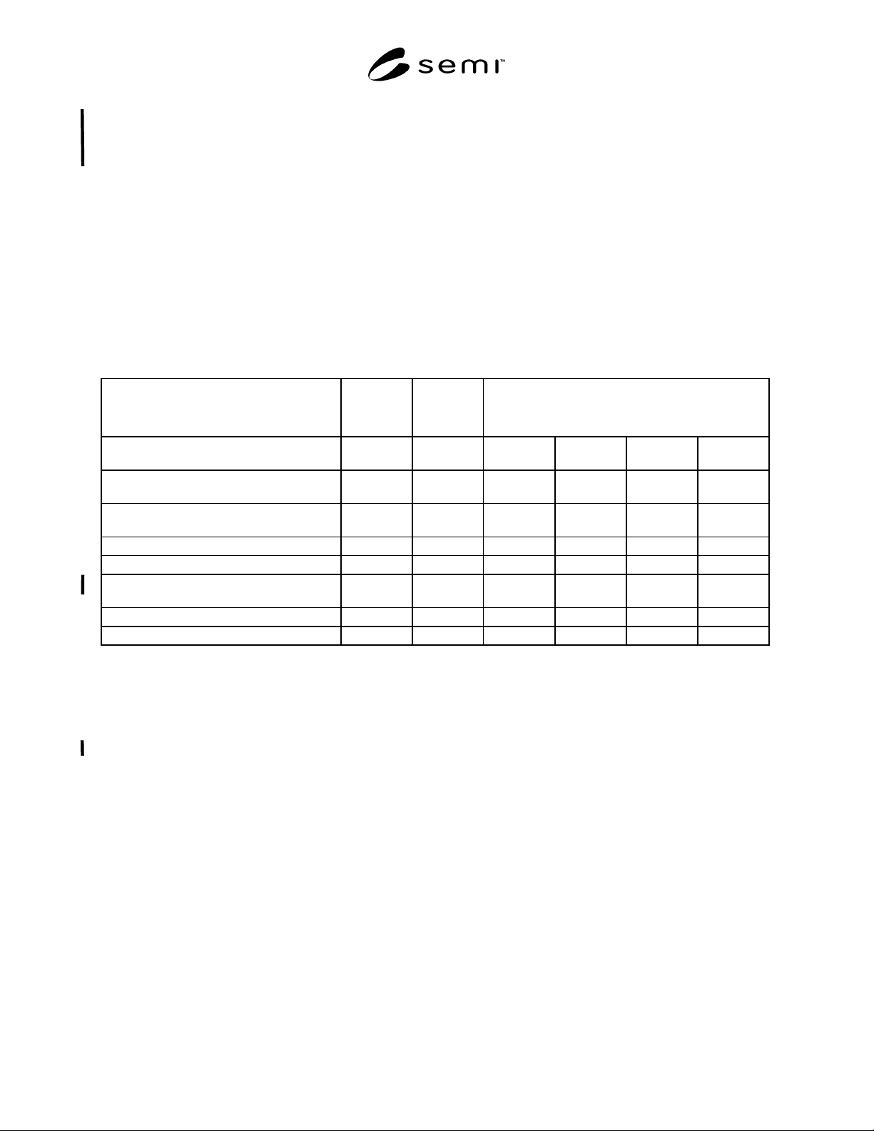
Table 1 SEMI Tool Accommodation Standards
Facility
Services
Process
Tool
Process Tool Subsystems
(internal distribution system for)
Guideline for
General Water &
Chemical
Solvent Gas
Facility Services Matrix defines utilities
available for tool
SEMI E51
Facilities Interface Specification defines tool
requirements of facilities
SEMI E6
Subsystem terms and references SEMI E49
High purity (HP) subsystem requirements SEMI E49.2 SEMI E49.4 SEMI E49.8
Ultrahigh purity (UHP) subsystem
requirements
SEMI E49.3 SEMI E49.5 SEMI E49.8
Subsystem assembly and testing SEMI E49.7 SEMI E49.6 SEMI E49.6
Tool packaging and delivery SEMI E49.1
4.2 SEMI E49 — Guide for Standard Performance, Practices, and Sub-Assembly for High Purity Piping Systems
and Final Assembly for Semiconductor Manufacturing Equipment
4.2.1 Purpose of SEMI E49 is to specify requirements for process distribution systems located inside of, and
provided with, semiconductor processing tools. (SEMI E49 acts as a reference document for the series of SEMI E49
standards, SEMI E49.1 through SEMI E49.8. See Table 1, SEMI Tool Accommodation Standards for an explanation
of the ten documents included in the SEMI E49 series.)
4.2.2 Benefits of the SEMI E49 series include assurance of compatibility in purity and performance between the
tool and facility distribution systems.
4.2.3 Roles and Responsibilities for SEMI E49 Series — Facilities engineer and installation manager submit
appropriate SEMI E49 requirements, either HP or UHP. Tool supplier uses information provided to ensure
distribution system compatibility.
4.3 SEMI E51 — Guide for Typical Facilities Services and Termination Matrix
4.3.1 Purpose of SEMI E51 is to communicate from customer to supplier factory facilities available at the utility
point of connection (UPOC) for a semiconductor tool.
4.3.2 Benefits of SEMI E51 include assurance of cost-effective and timely tool installation with minimum retrofit to
customer site.

SEMI E70-1103 © SEMI 1998, 2003 3
4.3.3 Roles and Responsibilities for SEMI E51 —
Facilities engineer and installation manager submit
utility specifications requested in SEMI E51 matrixes,
either typical or site-specific. Tool supplier uses
information provided about facility to assist in
configuration of the process tool.
5 Terminology
5.1 Definitions
5.1.1 acceleration cost — additional costs incurred to
complete the project sooner than the original scheduled
baseline plan.
5.1.2 as-built drawings — documentation describing
the actual configuration and dimensions at the end of
construction.
5.1.3 base build — installation of base building,
services, and equipment to establish functional
environmental controls and utilities to support
production equipment installation.
5.1.4 bidding — obtaining sealed quotes for a defined
scope of work.
5.1.5 burdened/unburdened — identification of costs
included or excluded from contractual labor rates.
5.1.6 capital equipment — equipment that is
depreciated according to tax guidelines for durable
goods. Generally has a value greater than $ 1,000.00 and
a useful life greater than 5 years.
5.1.7 change order — a document defining a formal
change in drawings, specifications, and/or scope of
work.
5.1.8 cleanroom — confined area in which the
humidity, temperature, particulate matter, and
contamination are precisely controlled within specified
parameters. Cleanroom classes are defined in
ISO 14644.
5.1.9 conditioned power — electrical power that is
manipulated to maintain specified tolerances.
5.1.10 construction — the set of activities that
transforms plans and specifications into functional
systems capable of performing to specification.
5.1.11 construction consumable — any material used
up during construction.
5.1.12 construction management — the set of activities
that define, direct, monitor, and report construction
activities such as workmanship, adherence to design,
cost, and schedule conformance.
5.1.13 contingency — a reserve of funds, time, and/or
material that is allocated to maintain schedule and
budget. A reserve for scope changes, unforeseen site
conditions, change in material prices, or unanticipated
events.
5.1.14 contract award — notification to the successful
bidder and subsequent signing of contract documents.
5.1.15 contractor — a licensed company hired to
accomplish a contractually specified scope of work.
5.1.16 cost of ownership (COO) — the total lifetime
cost associated with acquisition, installation, and
operation of fabrication equipment [SEMI E35].
5.1.17 cycle time, gross installation — total time to
install and commission process equipment, typically
starting from dock date to release for vendor startup.
5.1.18 cycle time, net installation — actual time
devoted to construction activities related to tool hookup
from dock date to ready for inspection.
5.1.19 damage — destruction or unintentional
alteration resulting in a liability.
5.1.20 dedicated truck — exclusive drayage of a
shipment.
5.1.21 design build — a contract method whereby the
contractor assumes responsibility for design generation
and construction to accomplish a specified performance
criteria.
5.1.22 design start — a milestone event that designates
the initial conversion of equipment specifications and
design concepts into engineering plans and
specifications.
5.1.23 detailing — generation of dimensioned shop
fabrication plans based on process and instrumentation
drawings (P&ID), field surveys, and configuration
verifications.
5.1.24 direct/indirect cost — direct costs are the cost of
anything physically associated with the installation,
removal, or modification of equipment. Indirect costs
cannot be associated with a specific piece of equipment.
Profit, overhead, and administrative costs are typically
considered indirect.
5.1.25 distribution system — the collection of
subsystems and components used in a semiconductor
manufacturing facility to control and deliver process
chemicals from source to point of use for wafer
manufacturing processes.
5.1.26 dock date — the date when the fab equipment,
including all ancillary components, is on-site at the
loading dock.
5.1.27 emergency power — electrical power supplied
by alternate sources or backup systems, like generators

SEMI E70-1103 © SEMI 1998, 2003 4
that come on line when the main utility power supply
fails.
5.1.28 equipment engineering — a group that focuses
primarily upon the electrical, electronic, and
mechanical characteristics of production equipment.
Depending upon the site and the fab area, Equipment
Engineering may be a distinct organization, or the
equipment engineering responsibilities may be handled
by other groups, such as Process Engineering or
Manufacturing Engineering. Equipment Engineering is
typically responsible for selection and physical
configuration of production equipment.
5.2 facilities interface specification — Documentation
provided by a tool supplier that contains the tool
requirements for utilities and installation as defined in
SEMI E6. So-called equipment data sheets are one
section of this document that also includes requirements
for safety, facilities services, shipping and receiving,
install, startup, acceptance, and training.
5.2.1 fast track — a scheduling method that eliminates
float and maximizes parallel activities, thereby reducing
overall project duration. Selective use of overtime is
typically used to reduce the duration of critical path
activities.
5.2.2 field change order — a document defining a
formal change in drawings, specifications, and/or scope
of work generated after contract award by on-site
personnel to incorporate conditions identified during
construction.
5.2.3 field fabrication — assembly and/or modification
of components on the job site to accommodate site-
specific conditions.
5.2.4 float — unallocated time created when tasks are
completed ahead of schedule or a task’s duration is less
than the allotted amount.
5.2.5 free on board (FOB) — goods placed on a truck
or other means of transportation at a point specified by
the seller without charge to the buyer, but with all
further transportation at the buyer’s expense.
5.2.6 gas cabinet — a metal enclosure that is intended
to provide local exhaust ventilation, protection for the
gas cylinder from fire from without the cabinet, and
protection for the surroundings from fire from within
[SEMI S4].
5.2.7 gas interface box (GIB) — an enclosure located
between the tool mainframe and facility services
containing components for pressure regulation and
filtration. Functions to consolidate all gas requirements
to single points of connection. Provides location and
ability to pre-facilitate tool hookups in advance of tool
delivery.
5.2.8 grounding — electrical wiring system to provide
earth ground.
5.2.9 hookup — the set of activities and organization
required to accept incoming process equipment, move it
into place, connect the equipment to all facilities, and
test the connections. The connection of all necessary
facilities and interconnects required to make the
equipment package fully operational. The hookup
activity is complete when all of the following are met.
• The equipment positioning and bolting down is
complete.
• The final equipment utility connections and
interconnects are complete, tested, and certified.
• The process piping certification is complete. The
wall system, including bulkheads as required, is
complete.
• The final decontamination is complete.
• Government inspections have been conducted as
required.
5.2.10 inertia base — a structural unit using mass
damping to attenuate vibration for production
equipment.
5.2.11 interconnect — connections between tool
mainframe and peripheral tool subsystem equipment
[SEMI E6].
5.2.12 issue for construction (IFC) — a milestone
event that identifies when drawings and specifications
are released to subcontractors for construction.
5.2.13 labor rate — the contractually stipulated cost of
labor.
5.2.14 laterals/sublaterals — intermediate facility
service distribution lines that run between mains and
equipment-specific isolation valves.
5.2.15 layout fixed — the milestone date when the
physical layout of equipment and components is fixed
and all stockholders complete approval sign-off.
5.2.16 local abatement — treatment of emissions at the
point of generation at the tool.
5.2.17 long lead materials — material requiring early
ordering due to availability or long manufacturing time.
5.2.18 mains/submains — central distribution lines
from a facility services source to which laterals are
connected. Individual equipment is not connected
directly to mains.
5.2.19 minienvironment — a localized environment
created by an enclosure to isolate the product from
contamination and people [SEMI E45].